Lab 2: Digital Input and Output with an Arduino
I first followed along with the “Digital Output” video.
Next, I wired up the Arduino with a pushbutton, making sure that the red jumper goes to the 5V and the black goes to the Ground. On the right, is the version with 2 LEDs and the LED is in series with the 220 ohm resistor; the yellow LED is connected to Digital OutPut 4. The red LED is connected to Digital Output 3, and the pushbutton is connected with Digital Input 2.


Then I connected my USB from the laptop to my usb connector on the Arduino Uno. Last step was writing the code with an if {} else {} statement, so that when the push button is closed the Yellow is turned on, and the Red is off.
—-
Digital Input + Digital Output Lab : Project
Next I tried to do a simple application using digital or analog input and digital output. I thought that doing a stoplight would be a good project to help me understand the concepts and information that were covered in the labs and in class. So, I decided to go forth and make an LED stoplight!
First I drew a schematic of how I imagined the circuit would be (see image below). Then I tried to wire the breadboard to the Arduino. From our labs, I knew that the push button would need to be set to DigitalRead, so I did that. I also connected the 3 colors (red, yellow, and green) LEDs to their own digital pins. I used 220 ohm resistors to connect the cathode side to ground.


Then, I wrote some psuedo code to help me figure out what commands I wanted to give the arduino (see image above). I came up with:
// if the switch state is low (the button isn’t pressed), the green is on
// else if the switch state is high (button is pressed), the yellow is on, then there is a delay before it turns green
Here is the code:

And here is the final product!!
—–
Lab 3: Analog in With an Arduino
Project 5: Control an LED with a Potentiometer
Followed along with the steps and was able to have the potentiometer control the brightness value of the LED. At first it didn’t work, but it was helpful to do the “analogWrite(ledPin, brightness);” and the “Serial.println(brightness)”. When it was wrong, I opened up the serial monitor and found that the potentiometer was working correctly because the value would change as I turned it right or left. I realized it was because I was doing “analogValue = analogRead(A0)” when it was on A1.
—
Analog Input Videos p.1 + p.2.
Followed along with the Analog Input p.1 videos.

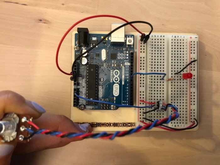
Project for Luv-o-Meter
This penguin’s Luv-o-Meter is done with the temperature sensor. And the more time your hand presses/ the hotter the sensor gets, the LED lights will light up more.
Apologies, this was done late in the night, and I just didn’t get a chance to properly document.
