Final Result:

—
Process:
For this week’s more open ended assignment, I was excited to do something fun and interactive! I thought about a couple of ideas, but eventually landed on doing a wheel of fortune spinner. Except that instead of spinning for money, the pointer would land on a random activity that the user would have to perform (i.e. clean the toilet, buy a plant, stretch, etc). The idea is that the finger spinner would land in a different place for a different amount of time each time the button is pressed.
I drew up a few initial sketches to show what I was initially hoping to achieve (heads up: this concept does change slightly, but the idea of a finger spinner remains the same). In the first few drawings, such as the image below, it was designed to be just a flat board with the push button on the side. Included are all the separate parts that would make up my interactive piece.
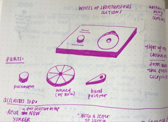
sketch of initial concept
However, I realized when I was getting my assets ready to build that this flat surface would be a challenge. The motor would have to be tucked away somewhere. So, I decided to redesign the form of the interactive piece. The image below shows the updated design.
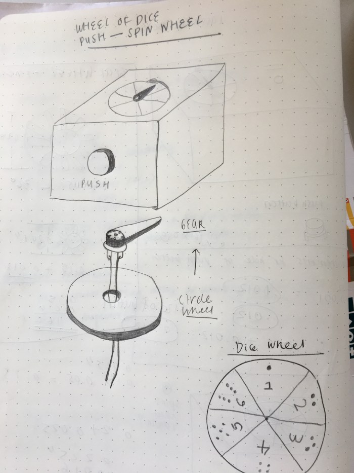
updated sketch for spin-the-wheel idea
I also updated the design so that if it were a box the push button would be in the front, as a way to save wood and space. Also, my friend went to a game night last Thursday and told me how they had an issue with throwing the dice because there was no space on the table. From this, I realized the spinner could act as a dice. For the people who have no space to throw a pair of die, they could just use this push button dice wheel. Not to mention, the updated design was a 3″x4″ box and there was no way I would be able to comfortably fit text phrases on the wheel.
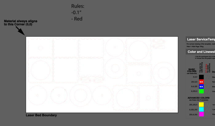
I found a teeth box design I could use online (why reinvent the wheel, right?). After downloading the online illustrator file, I opened it up and tweaked the design to include the holes for the push button, the wheel, and the finger. Below is an example image of the illustrator file with all the parts (and duplicates) for the piece.
Side note, the finger was a fun challenge. To draw the finger, I needed to have an accurate measurement of the motor’s gear. With help, I used a caliper to measure the exact diameter of the wheel’s outer and inner rim. The image below shows the calculations that helped me create the pointer with an accurate hole for the gear to fit through.


After finishing up the illustrator file I was ready to use ITP’s Laser Cutter for the first time! I first used cardboard to help me prototype and make sure my drawings were accurate. After printing, I fit the pieces together and thankfully the pieces for the box fit well. See the process photos for that below.


The only issue was with the circle piece bottom support piece for the wheel. It was too big and I needed a way to have the gear fit well into the bottom layer. So I altered the illustrator file to include a couple of new pieces that considered the gear. Then I decided it was time to laser cut on the cheap plywood! See the exciting process below (not that exciting maybe, but this is my first time!).
Now onto the last parts of the fabrication/ building aspect: assembling and soldering the push button. This part of building the box went by with little hiccups, it was a meditative and straightforward process of gluing the pieces together. See images below.


Now the final step for me was drawing the schematic, wiring up the circuit, and writing the code! I based the circuit schematic off of “Project 9: Motorized Pinwheel” of the Arduino Uno book. I forgot about this project, and had not realized there was already something so similar to the dice wheel idea. I’m so thankful for it, because there were so many parts to the circuit design that I wouldn’t have gotten right if it were not for this chapter in the book. I probably would not have added the diode ( I had no idea about the back voltage and still am not sure if I completely understand). So both the circuit drawing and the code are based off of this.
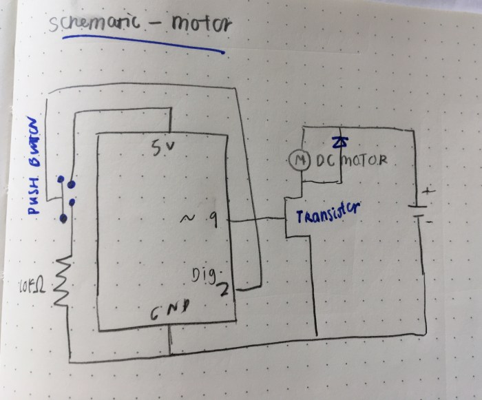
circuit drawing

image of the circuit and a video of the motor spinning when the push button is pressed.
Here is my initial code, which is taken from the Arduino Uno book.
” const int switchPin = 2;
const int motorPin = 9;
int switchState = 0;
void setup() {
pinMode(motorPin, OUTPUT);
pinMode(switchPin, INPUT);
}
void loop() {
switchState = digitalRead (switchPin);
if (switchState == HIGH){
digitalWrite(motorPin, HIGH);
} else {
digitalWrite(motorPin, LOW);
}
}”
—–
It was very beneficial to have this project as my foundation, but I’m running into challenges with having the push button and finger interact the way I want it to. It is supposed to spin for a random amount of time when the button is pushed once. Right now it is just spinning whenever the button is pushed.
Then, I thought that maybe it had to be a analog output since I am trying to have the push button read varying times. However it didn’t work. Below is the code for that:
“const int switchPin = 2;
const int motorPin = 9;
int switchState = 0;
void setup() {
pinMode(motorPin, OUTPUT);
pinMode(switchPin, INPUT);
}
void loop() {
switchState = digitalRead (switchPin);
// if switch state is on then motor spins at random intervals of time
if (switchState == HIGH){
analogWrite(motorPin, random(100, 9600));
}
//switch state is off
else {
digitalWrite(motorPin, LOW);
}
}”
—-
After going to the professor’s office hours, Tom helped me figure out what code to write in order to get the spinner to interact the way I intended it to. I realized that I needed to set a variable for the delay length and define the variables for the delay length variable within the “void loop()” function. I also needed to add a delay between the “if ()” and “else()” statement. It was a very helpful session; it also helped me realize what I should focus on moving forward. I am specifically struggling with writing code from scratch, so I need to devote more time to improving my programming skills.
With a lot of help from Professor Tom, here is the code that tells the motor to spin at random amounts of time when the button is pressed:
“const int switchPin = 2;
const int motorPin = 9;
int switchState = 0;
int delayLength = 0;
void setup() {
pinMode(motorPin, OUTPUT);
pinMode(switchPin, INPUT);
Serial.begin(9600);
}
void loop() {
switchState = digitalRead (switchPin);
// if switch state is high set the delay length and start the motor
if (switchState == HIGH){
delayLength = random(200, 1000);
digitalWrite(motorPin, HIGH);
Serial.println(delayLength);
delay (delayLength);
//if the switch state is low stop the motor
} else {
digitalWrite(motorPin, LOW);
}
} ”
And below is a video of the near final result. The last part is to add the dice wheel graphic.
