Updates on Week 10
a.) Project Proposal
b.) Schematic Diagram
c.) Diagrams for Production
d.) Timeline + Bill of Materials
e.) Prototypes
f.) Analog Input
g.) Web Design
—
a.) Proposal Presentation:
This proposal pdf was put together for ICM, but serves as a helpful guide of the project’s why, what, for who, and how.
Solar_Proposal_Presentation_20181113 EL2
—
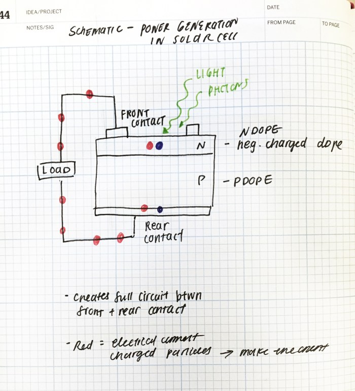
b.) Schematic Diagram:

—
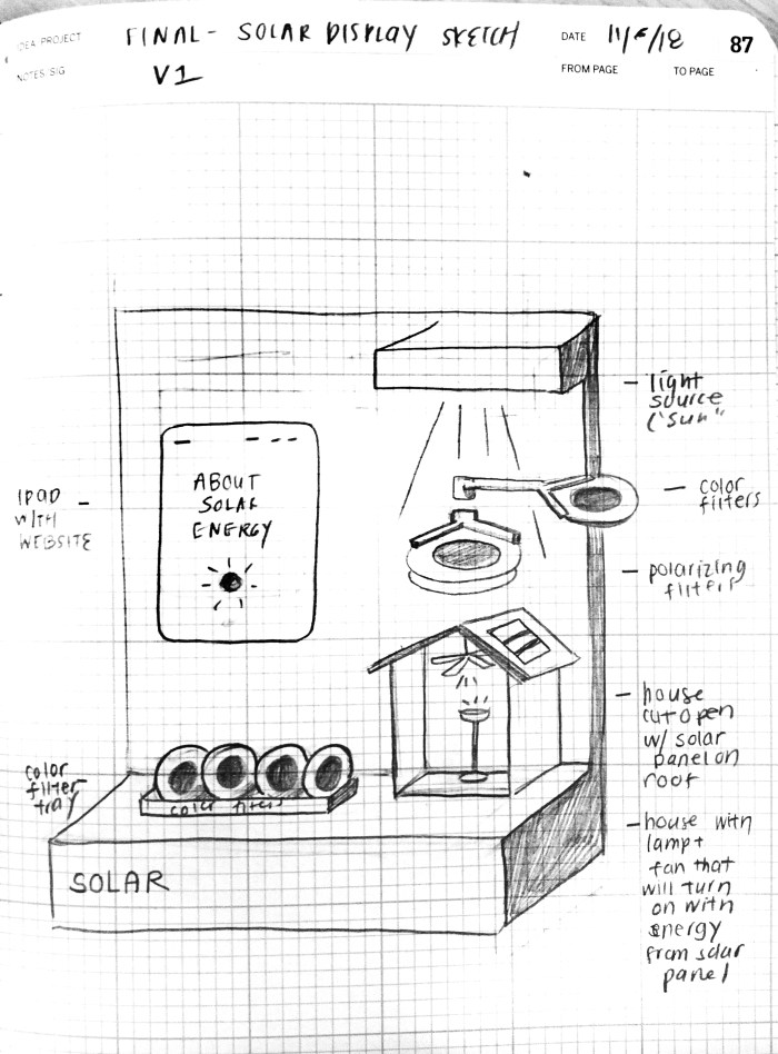
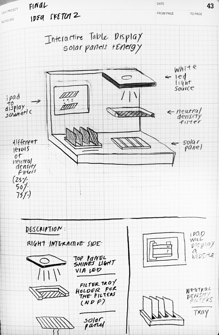
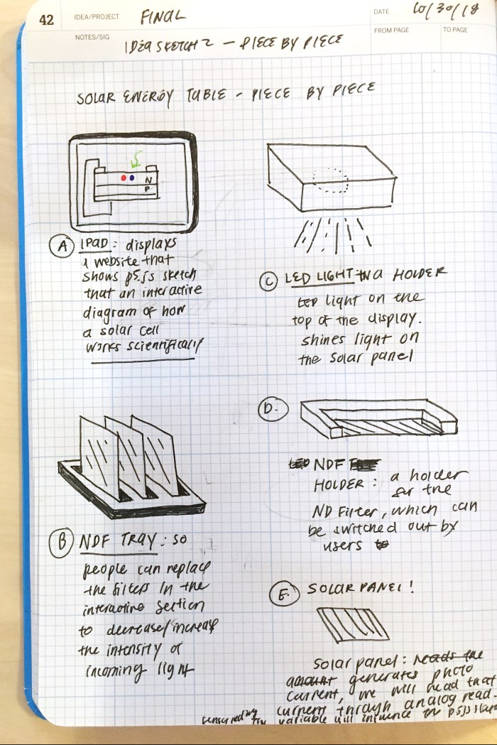
c.) Diagrams for Production


 The below image is the original diagram drawn for the version of the house with a lamp and fan. This plan has changed. See new diagram below.

—
d.) Timeline + Bill of Materials: https://docs.google.com/spreadsheets/d/1zA4OJrYoYLFRfl6XcdlWMDRCV-Dq8sbgWobO5o2G_kc/edit#gid=0

timeline and tasks
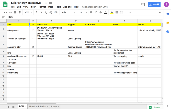
bill of materials
e.) Prototype:
Initial cardboard prototype to better understand the scale, proportions and positioning. The house is missing from this because I realized that the house would need to hide the wires of the fan and lamp as well as the Arduino. I found a ball bearing at Canal Plastics that I thought would work great for the polarizing filters.

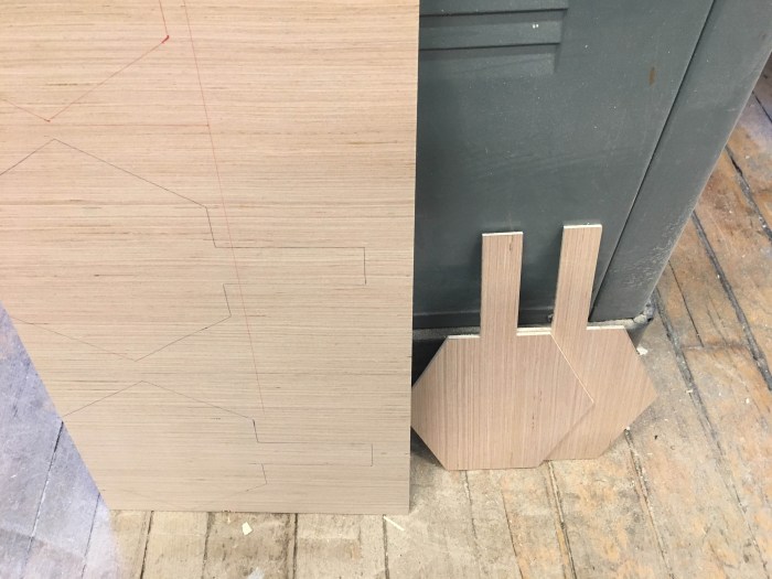
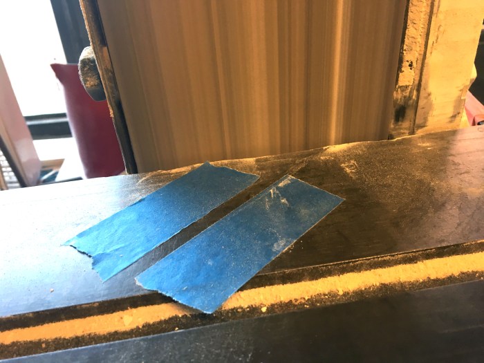
Here are some process photos, which include the sketches with rough dimensions.


Prototype of the house:
Knowing what to do with the house has been tricky. I did this wooden prototype but felt that it was too tall. I did a cardboard version that had an attic and an extra bottom layer so that I could hide the motor and the arduino and lamp. What I don’t like about both designs is how much shadow is created by the roof. The lamp and fan will be barely visible when seen from above. See images below.


So after doing these prototype houses I decided to switch the design of the house so that it will not have the front open. Instead, there will only be windows that will dim or light up depending on the reading from the sensor. This change was also partially influenced by this inspirational piece below. This simply and beautifully communicates the idea.
http://www.hashemjoucka.com/work#/wind-turbines-interactive/
—
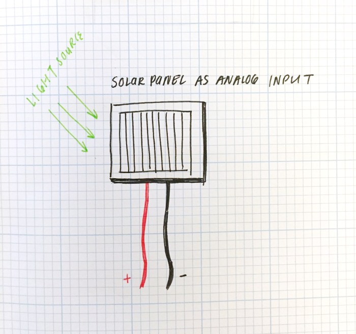
f.) Analog Input with Light + Solar Panel:
First was following along analog input to serial lab again in order to have the p5js sketch communicate with the serial connector and arduino. Below is the video for that
Below is the video and arduino code that reads the analog input from the solar panel and writes analog write (PWM) to have the LED light correspond to the sensor reading.
p5js code: https://editor.p5js.org/elinsterz/sketches/ryirTRP6Q
Arduino code:
“void setup() {
Serial.begin(9600);
pinMode(9,OUTPUT);
}
void loop() {
int solar = analogRead(A1);
int mapSolar = map (solar, 0, 1023, 1, 255);
Serial.write(mapSolar); //translates to binary
analogWrite(9, mapSolar);
}”
—
h.) Web Design
Rough look and feel of the diagram and site is below. Steps will be revealed when the user hovers over the number icon. The motion of: photon —> electron-hole pairs –> traveling through circuit –> reunite at the rear will still continue and be dependent on how much light is showing through.