Idea:
When the user shows this hand drawn x symbol to the screen, which is often seen when the console shows an error in your code, a coding syntax character will appear. Associated with each character is a little blurb about the syntax and some helpful reminders when using it. This AR piece is intended to be a educational tool and hopefully a momentary relief from the troubleshooting process of coding.
Below are some videos that show how this piece would work.
Curly Brackets character rendered in HD.
—
Process:
1.) Sketches of the idea, which changed significantly from the original concept that used the 3d text. Instead of having 3d text over the image tracker that said “Class not making any sense?”, there would be a 3d character of a syntax character. Below are some sketches of various characters I was hoping to model.
—
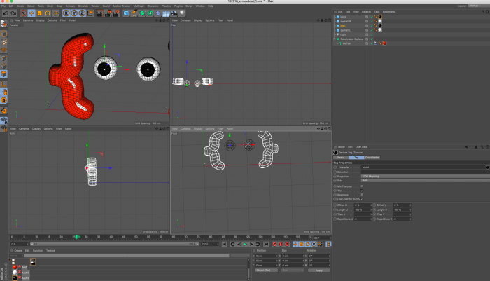
2.) Next was modeling the character in Cinema4d. I am happy I got a chance to use this program, but I am still familiarizing myself with it. So this step took a little longer than I had hoped. Nonetheless, it was fun and I was able to model my character. Below are some screenshots of this process.
—
3.) Simultaneously, I was following along with the roll a ball unity tutorial (see video below). This was so helpful and helped me a lot. Most importantly, it was good to see that it was possible to do text. However, this would prove harder than expected to get text to animate.
—
4.) I then wrote script for the character.
—
5.) Next was animating the text. I attempted many different things to try to get animated text. It was easy to get text, but I wanted to create a animated dialogue, so that each line would appear one at a time.
For this week’s assignment to create a sketch that uses an external data source. I decided to proceed by finding dataset regarding suicide rates in different countries and use the table function of p5.js to help visualize the rates.
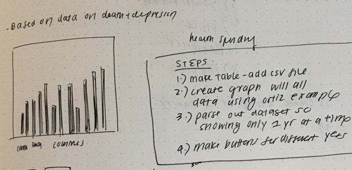
1.) I knew I wanted to focus on data that dealt with death, mental health or happiness levels. Eventually, I decided to focus on visualizing the data about suicide rates in different countries. I found the data set on this github account: https://github.com/liadkeller/Suicides-Data-Analysis-DSE200X
Then I sketched out the idea and wrote a to do list for tackling this. See sketch below.
—
2.) After I decided what type of data I would be working with and how I wanted to display it, I followed along with the 12.2 Ortiz Table Example in “Make: Getting Started with p5.js”. Since the 12.2 example deals with loading tables, I knew this exercise would help me when working on my own sketch. This was an extremely helpful example as it covered how to create the lines for the graph and how to map the data to the graph. It was also extremely helpful to know the specific syntax for working tables (i.e. getRowCount(), getNum()) Here is the code for that: https://editor.p5js.org/elinsterz/sketches/rJm0d1Vn7
This example was using vertex, and I knew I wanted to use bar charts for my sketch. So I changed this to be a bar chart instead of a line graph. Here is the code for that: https://editor.p5js.org/elinsterz/sketches/BJRh5G42Q
—
3.) After better understanding how csv and the loadTable() works, I imported the suicide rate data to the ortiz example that I just worked with. A couple of elements I had to change were the mapping coordinates and adjusting it to fit the larger canvas.
4.) The sketch above is not interactive at all; it displays all the suicide rates of all the countries over with all the years available. So for my next step, I worked on just displaying the data set for 1 country first: Australia. I also tried to use the button feature so that when you press on the button, the data for Australia will show.
In order to do this I had to create a variable for the button. Then “createHeader()” function was made to store the createButton dom function. A callback function was created so that when the button is pressed, it will perform “function aus()”.
The function “aus()” was created for the Australia button. The function has a for loop that goes through each row of column 1 (the country code column). If the loop runs into a string called “AUS” it will get the number of each row in column 3 (suicide rate). Using the data retrieved in column 3, it will draw an ellipse randomly. ( I just did ellipses at random places as a test ).
—
5.) Then I tried to use this Australia button sketch to make the bar chart (that maps each year from 1955 – 2005), instead of randomly placing ellipses. This was no doubt the most frustrating and challenging part. After many sad attempts, I eventually realized that I needed 2 for statements. The for statement from before that finds the rate for all the codes with “AUS”. There is another for statement that does the mapping function from the ortiz example.
Another addition (that took forever to get to ) was adding “i++” after the first for loop. This is to make sure that every time the code runs through the if statement, the code will go to the next index in the array.
The code is saying: find the strings in column 1 that has “AUS”. If it is “AUS” then get the number in column 3, which is called “suicideAus[]”. Then go the next row that has “AUS” and perform the same task. If the first for loop is complete, go to the second for loop and run through the array of “suicideAus[]”. Map the item in “suicideAus[]” to the x and y coordinates on the canvas. The x maps the number of items (column 1, years) in “suicideAus[]” the x coordinate. The y maps the suicide rate (column 3) to the y coordinate. Draw a rectangle using the x and y coordinate of the map function.
6.) Last step is making 4 -5 buttons for all the different countries. I ended up choosing only the countries that went back enough years. Also I wanted to keep the years consistent between 1955-2005, so I had to delete some years of some countries that had data before 1955. Last and easiest step is styling the page a little more by adding a different color for each country and creating a title.
This week I definitely felt like I was not completely getting the material. After following along with all the Coding Train videos I still felt like I would not be able to write any of the data code from scratch. I’m hoping that with more practice I will get much better and be able to not rely so much on other people’s/ example codes when I work on my own sketches. For the homework assignment, I was really just taking bits of code from the book, bits of code from the coding train example, bits of code from someone else’s sketch to try to make it work for myself. At some point, I had all the elements I wanted in 3 different sketches and was trying to compile it all, which took a lot of head banging to figure out. It is rewarding when it does come together, but I’m just constantly self doubting myself. And when I couldn’t make my original idea work, I kept switching ideas, trying to find new data that was perhaps easier, more simple. This is a problem. I need to stick with it. In this case I did go back to my original idea, but I wasted so much time just trying to find simpler data and brainstorming ideas (that I didn’t even end up using).
Another thought: I am understanding the csv and loadTable() a little more, but I still need so much practice with using APIs and JSON. Because I only tackled the Table for my homework sketch, I missed out on familiarizing myself with APIs and JSON, which is definitely equally interesting and helpful to know. I will have to find time to go back to this section and review.
Questions + Notes:
I feel like there are so many questions and random notes that I stumble across, so I’m trying to record my findings and confusions in a more organized way. Therefore, I’ve created this google doc so that I can remember for myself. It’s also helpful for when I meet with the residents for help, so I know exactly which questions I need clarification on: https://docs.google.com/document/d/1SxqH8ZKcj5BHDhj6kd7POKk8_rkW7q4olZZwaDr6cwU/edit
b.) Program p5.js for serial communication
See video below for example of the keyPressed() function and mouseDragged() function
c.) Mousedragged() function in p5js to change the values displayed on the p5.js canvas and the LED brightness.
d.) keyPressed() function in p5js reading the pressed keys 0-9 and the LED changes depending on the # pressed.
e.) keyPressed function to read H or L in order to effect the LED.
—
Notes for self:
1.) “println” doesn’t work in p5.js. It has to be “print”.
2.) “serial.read line()” in p5.js works with “println()” in Arduino. p5.js reads ASCII and arduino prints ASCII.
3.) “parseInt()” in Arduino: converts p5.js string into an Arduino integer. It parses out the ones that are not integers.
—
Questions:
1.) For the keyPressed() function, why is the “outByte” defined as a “byte” and not “int”, like the mouseDragged() function? I will try both and update the results.
2.) Tried sending ASCII encoded strings with Arduino and I think I need more clarification with parseInt(). Why and when do we use parseInt()?
For our Halloween project, Chunhan Chen and I collaborated with NYU’s Graduate Musical Theatre Writing Program to create an interactive crystal ball for their fortune teller room. The idea is that 2 – 3 guests would enter the room and have their tarot cards read by the NPC (non-player character). In the middle of the reading, the alien ghost that haunts the town of Twyp would interrupt the scene and reveal clues about the death of the professor. We achieved this crystal ball using a touch sensor that would trigger this premonition animation. In the crystal ball’s non-triggered state, it would loop through various tv show clips from the 1950’s, which is the setting the town takes place in.
Process:
There were many parts to our 2 week long process, so this documentation is broken down into the chronological steps that were taken: a.) brainstorm, b.) idea + technique, c.) triggered state animation, d.) normal state animation, e.) fabrication, f.) coding, g.) testing, h.) putting it all together, i.) in action (to be added in after the musical show) , f.) reflection (also to be adding after the musical).
a.) Brainstorm
Before our first get together, I sketched up 4-5 ideas. Only 2 of them I was actually interested in pursuing further. After discussing, we agreed we were more excited to create a project for a group with a practical need.
Chunhan shared with me some details of the musical meeting and described to me the room that she was most excited to work on: the gourd museum/ blue room. This whole room seemed fabulous, so we got straight into emailing with Danny, the one coordinating the musical, and Briana, who was in charge of the Blue Room. However, we soon found out that 2 other ITP groups were already working on that room. We decided to look at the GMTWP’s Wish List and choose from there. The interactive on that list that we were most excited for was the Crystal Ball for the Fortune Teller Room.
Luckily, the interactive for this room was not taken. The very next day we were able to meet up and discuss their thoughts.
b.) Idea + Process
Our first meeting with Professor Robert and Wilson was extremely helpful as we went over more specifics beyond just having a crystal ball (i.e. what is the message the crystal ball is trying to tell, how does it relate to the whole musical storyline). Robert also had a crystal ball handy with a hole cut out ready to be used!
The idea is that Wilson will be reading tarot cards to 2-3 of the guests on the night of the musical. And in the middle of the reading, an alien ghost spirit would interrupt with a premonition of sorts; this premonition would reveal some details about the murder that will occur in the story’s overall plot.
Since the small town of Twyp is set in 1950’s, they had an idea of playing classic tv shows of that time when it was in it’s normal state. In this way the crystal ball would also act as symbol of a tv set.
We also talked about having an interaction that Wilson would be able to perform in order to unlock the triggered state. Some ideas that came up was trying to trigger the crystal ball with 3 claps or a specific melody. This eventually changed to be just touch, because we were afraid that there would be too many other sounds in the room and the sensor wouldn’t be able to read the sounds properly.
For creating the crystal ball effect, Professor Tom mentioned a technique called the Pepper’s ghost. This technique creates a projection of the graphic using the reflection created from a plexiglass/clear surface tilted at 45 degree angles. Chunhan and I both researched online about how to create this effect; here is a google sheet with some links we compiled.
The diagrams below explains how the Pepper’s Ghost effect works. Source: comsol.com
See a schematic and quote below regarding the pepper’s ghost. Here is the link of the source by Jason Poel Smith.
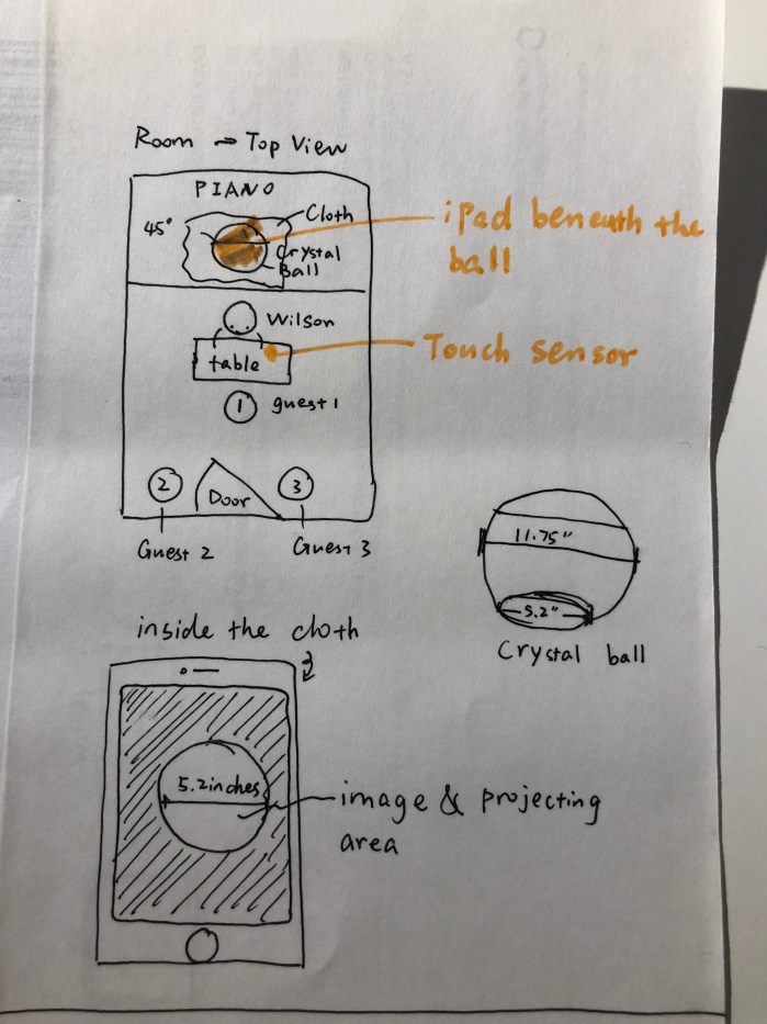
After researching, we sketched out how it would work in the fortune teller room. See diagram below.
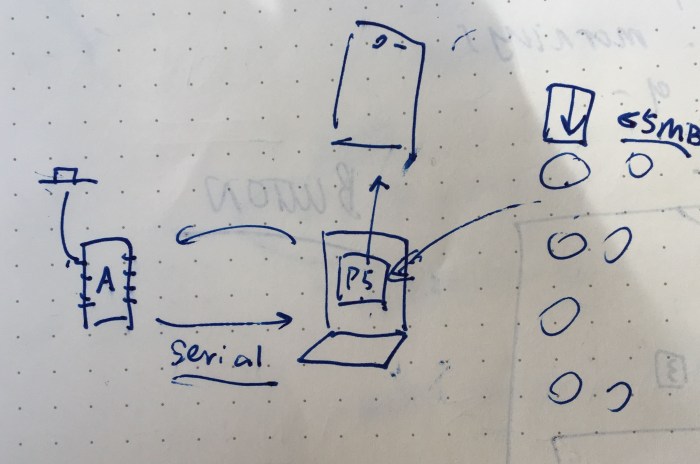
Chunhan also diagrammed out how the Arduino would be connected to the serial and the p5.js sketch that would be loaded on a browser which the iPad would be loading as well. See sketch below.
For the tasks we agreed to divide up the work (since we are limited in time) and do a skill share session when we are further along with the project.
Tasks:
1.) Creating a web page that that the animations would be displayed in. It would need to be in the same 5.2 circle shape that the diameter of the crystal ball is. – Chunhan
2.) Gathering the tv clips. Animating the “triggered” state with all the hints. – Emily
3.) The interaction of finger hitting on the force sensing resistor or touch sensor so that it would start the “triggered state.” – Chunhan
4.) Fabrication of the base so that the crystal ball will not move around/ change positions when it is on top of the iPad. – Emily
5.) Prototyping in space and email communications with Robert, Wilson and Danny – Chunhan and Emily
c.) Triggered State Animation
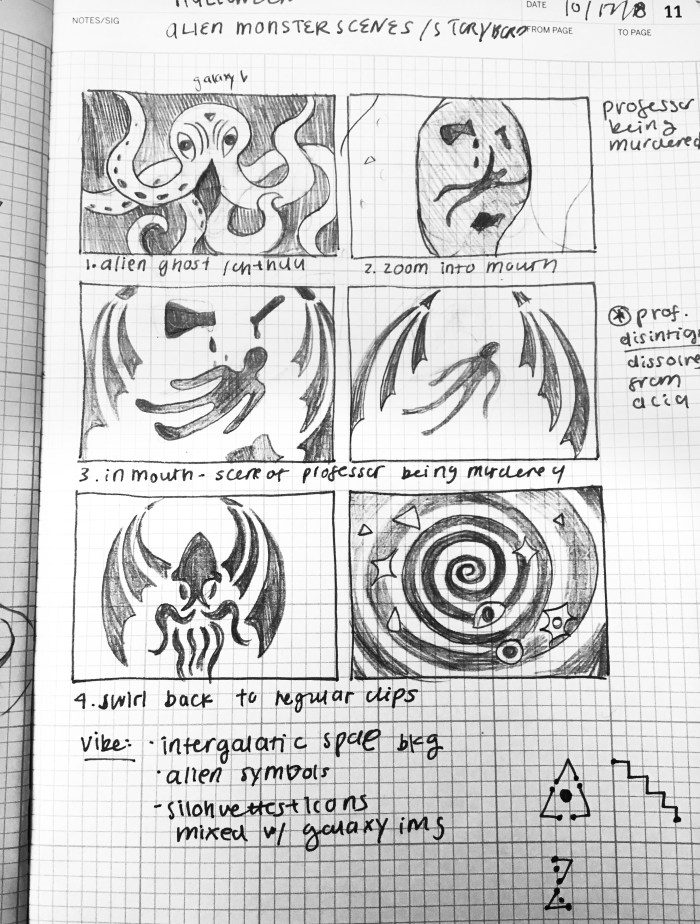
For the animation, I tried to incorporate all the elements and ideas that Professor Robert Lee, Wilson Weber, Chunhan and I had discussed in the prior meeting. The main points after our talk was that the triggered animation should: 1.) allude to the murder of the professor (potentially by acid), 2.) include the Cthulhu alien monster symbol, 3.) have a Twilight Zone, intergalactic, sci-fi vibe, 4.) potentially match the gypsy fabrics that would be used in the fortune teller room. From this very helpful information, I sketched up a quick storyboard:
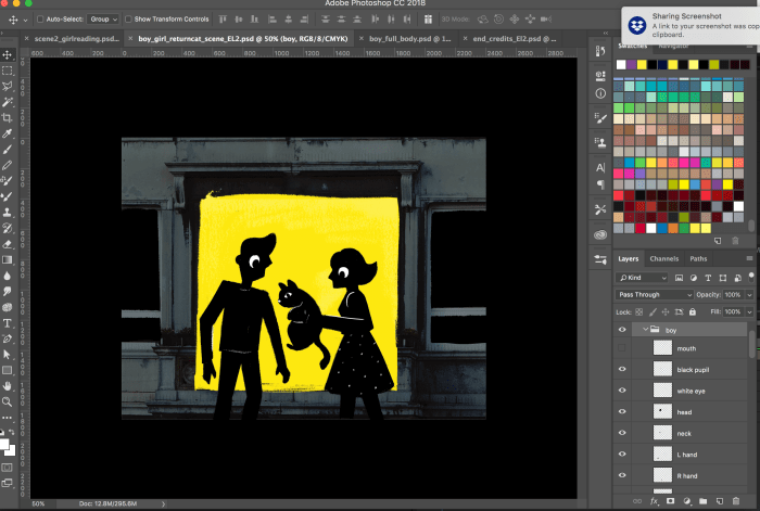
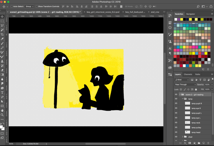
The next step was drawing the scenes in photoshop. Below are some screenshots of the Photoshop files with all the assets separated into different layers ( to make it easy to animate in After Effects).
This slideshow requires JavaScript.
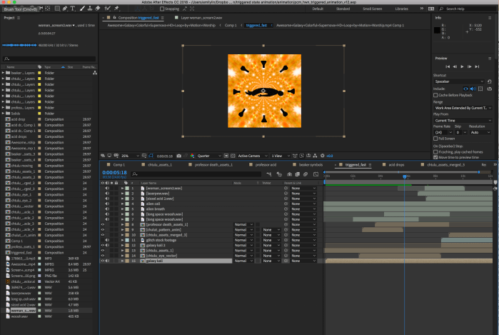
Then I brought in these into After effects and started animating! Love having the chance to animate for a project! Below are some screenshots of the process of working in After Effects.
Side note & shout out: the cool galaxy animation I used for the background was initially taken from this clip. I downloaded it and was able to manipulate it using After Effects’ Kaleidoscope and Flomotion effect to create some animated gypsy like patterns!
Here was the first version of the animation.
We wanted to share this with Professor Robert and Wilson because we were not sure if this animation was giving away too many clues about the murder. It is also good to just check in and make sure we are on the right track. So, we emailed them this animation and some updates on our progress last Thursday.
Almost immediately they responded and let us know that the animation wasn’t too explicit and they loved where it was going! Big yay! They were also kind enough to give us some helpful direction and great ideas. Robert mentioned that he thought we could drop even more hints and incorporate the idea that the professor in the story is a woman. He was also hoping for it to evoke some H.P. Lovecraft feel and suggested adding in tentacles and eyes (as a lot of H.P. Lovecraft artwork incorporates those elements). Wilson agreed and also suggested possibly incorporating the Cthulhu symbol at the end.
This was such helpful feedback and I got to work on incorporating those changes by including the tentacles and eyes, making it more sepia-toned, adding a women’s voice screaming at the end. Chunhan also mentioned that the animation gif had to be under 5MB in order for it to be loaded in p5.js. Therefore, I sped up the animation so it would be able to export under 5 MB. Below is the newest version with all the edits mentioned above.
Then the mp4 was exported into Photoshop and exported into a low-res gif. So the version that will be seen via the reflection in the crystal ball, won’t as crystal clear as these mp4 videos seen here, but I’m hoping the general vibe and storyline will still show through.
d.) “Normal State” Animation
The idea that Robert and Wilson came up with is that in the crystal ball’s “normal state” there would be classic 1950’s television clips (i.e. ” Twilight Zone”, “Bewitched”, “I Love Lucy”).
Chunhan mentioned that it would take the browser longer to load if there were too many clips, which is why we decided on 5 tv clips. I searched through Youtube and made a playlist with some episodes, and tried to find a good variety between the “everyday” life tv shows like “I Love Lucy” and the more absurd horror like shows, such as “The Twilight Zone.”
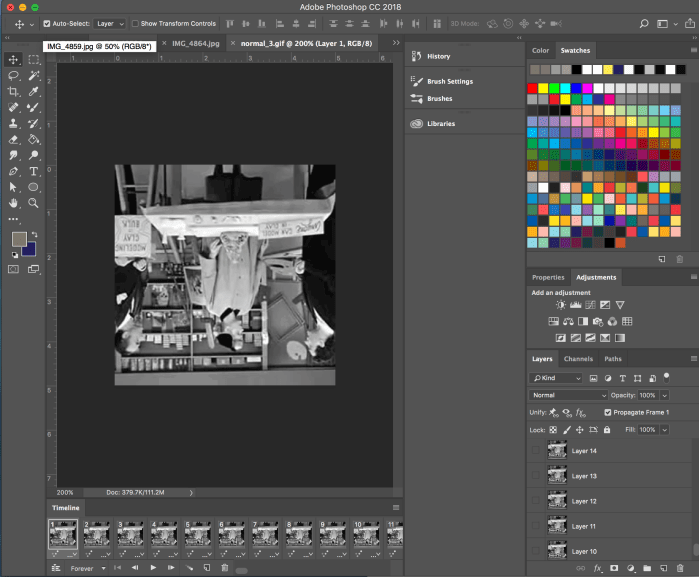
I then took these clips and edited it down to 10 seconds. Then these clips had to be turned 180 degrees because the screen will be reflected on the transparent sheet inside the globe. Below is a screenshot of the process.
Chunhan was thankfully careful enough to notice that one of the clips was not reverted. So, she helped turn it upside down herself. She was then able to test it out in the code.
e.) Fabrication
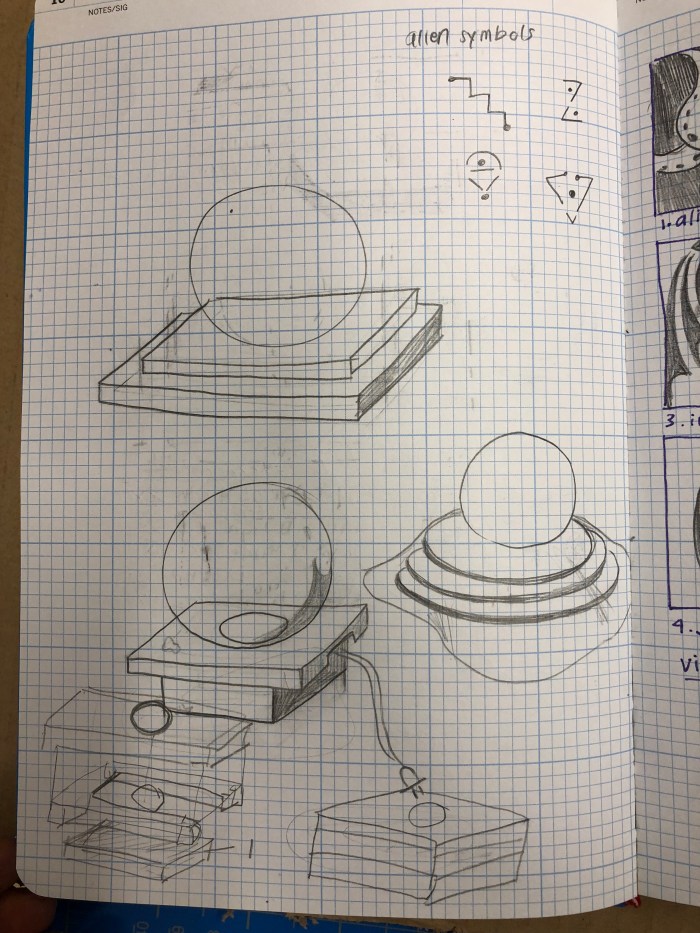
Initially we had just talked about putting a black fabric over the iPad and cutting a hole out. However this would both not provide a sturdy connection between the iPad and the crystal globe and it would not look great. We needed a way to position the iPad in relation to the cutout hole from which the iPad will project it’s circular image. First step was sketching different designs out. See sketch below.
After sharing the designs with Chunhan, we decided on which one would work best for us. This box design works like a drawer so that there is an insert that the iPad would be placed on and be able to slide into the base of the box. This would do 3 things: 1.) place the iPad with the circle animation in the exact location in relation to the crystal ball, 2.) have a nice opening for the iPad charger, 3.) look more structurally sound and considered.
Next was getting precise measurements for everything, including the exact placement that the circle on the iPad would be with the cutout of the hole for the top layer of the box. The insert for this iPad was a fun challenge: it required consideration of the diameter of the inner rim of the box, and to keep in mind the depth of the wood that will be used. Below are some notes, measurements and sketches that were taken to design the box and get it ready for laser cutting.
This slideshow requires JavaScript.
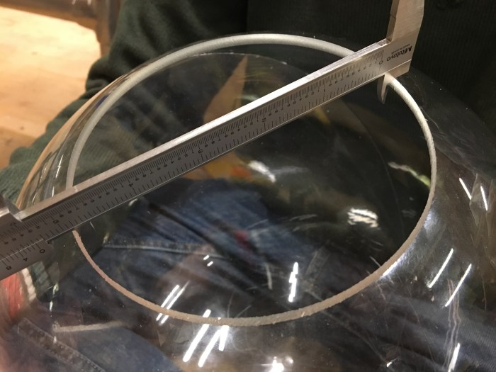
I got the measurements for the depth of the iPad Pro and inner diameter of the crystal ball using the caliper.
Next came laying out the individual parts in illustrator to get it ready to be laser cut. I used an online box template and adjusted it to be the dimensions we had measured. After that was done it was ready for laser cutting on the cardboard prototype. See images below of the illustrator files. Then I assembled the cardboard prototypes together.
laser cutting illustrator file
illustrator diagrams
cardboard prototype put together
cardboard iPad insert
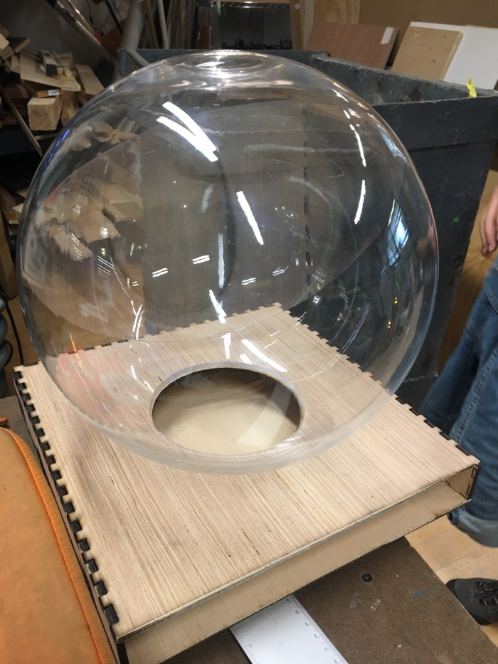
The issue that we ran into after putting this prototype together was the circle cutout on the top layer. We had hoped that the bottom of crystal ball would be able to fit snugly in the hole so it would be a good support for it. Unfortunately, it would be able to work. I tried cutting out a bigger hole, but the bottom of the circle was still not able to properly fit in the hole (see images below for reference). The solution was to just make the hole smaller and just glue the crystal ball’s bottom rim to the surface of the base.
After the design and measurements were adjusted in Illustrator, the wood version was laser cut and assembled!
The insert worked! See video below.
One big mistake was the choice of wood. This 3/16″ plywood was cheap but it was not great wood for laser cutting. It was not cutting the wood cleanly and it was also taking the laser cutter at least 6 runs before the cuts would go through the wood. Many times I had to use force the cutouts from the wood by hand and chisel them out as well. This was unfortunate because it would ruin the wood and create these tears in the wood. It also created a dark and ashy burn mark on the edges. See the image below. Lesson learned: research different types of woods and try not to laser cut anything over 1/8″ thickness.
Next is to sand and spray paint! This was a straightforward and fun process. See images below. I ultimately decided to not spray the support stands and the insert inside the box because I was afraid that the rougher texture of the spray paint would not allow the sanded down wood to slide into the box as nicely.
Then we put it all together with the work Chunhan has been doing with the touch sensor and p5.js!
f.) Arduino and p5.js (See Chunhan’s blog for detailed documentation)
Chunhan coded it so that when Wilson hits the sensor 3 times it will set the “triggered” animation. When he hits it 2 times it returns to the “normal” state.
I set the “trigger cipher” to 2, which means that when Wilson hit the sensor for twice, it will change the triggerState to “1” and then reset the switchCount value to 0. Similarly, a “normal cipher” of 3 means that when he hit the sensor for another three times, it will change the triggerState to “0” and then reset the switchCount value to 0. – Chunhan Chen
Here is the final code that Chunhan wrote the crystal ball:
” (1) Arduino part
const int switchPin = 2;
boolean triggerState = false;
const int triggerCipher = 2; //touch twice to toggle the state to “triggered”
const int normalCipher = 3; //touch three times to toggle the state to “normal”
int switchCount = 0; //recording the number of times people touch the switch
int prevSwitchValue = 0;
// Starting the “hand-shaking”
while(Serial.available() <= 0){
Serial.println(“Waiting Data”);
delay(300); //wait 1/3 second
}
}
void loop() {
checkButton();
checkTriggerState();
if (Serial.available()>0){
int inByte = Serial.read();
//send a new message to p5.js if it has been triggered
Serial.println(triggerState);
}
}
void checkButton(){
//read the touch sensor value
int switchValue = digitalRead(2);
//if the switch has changed,
if (switchValue != prevSwitchValue){
//debounce the switch;
delay(5);
//and that the switch is touched
if (switchValue == HIGH){
switchCount++;
}
}
prevSwitchValue = switchValue;
}
void checkTriggerState(){
if (triggerState==false){
if (switchCount >=triggerCipher){
triggerState = true;
switchCount = 0; //reset the swithCount to 0.
}
}
if (triggerState==true){
if (switchCount >=normalCipher){
triggerState = false;
switchCount = 0; //reset the switchCount to 0.
}
}
}
(2) p5.js part
/*
Holloween CrystalBall
P5.js side for Physical Computing mid-term
Made by Emily Lin and Chunhan Chen
Oct 22 2018
NOTE: You have to use “python -m SimpleHTTPServer” in the terminal.
Then open a tab and type “localhost:8000” for the address to get access to the music file.
If you are viewing from another device, use “ID address:8000” instead. Make sure the device share the same local internet with the laptop.
Also you should keep p5.serialcontrol application open while running the program.
triggeredSound.amp(1);// set the volume of the sound to normal.
// triggeredSound.playMode(‘restart’);
// triggeredSound.play();
triggeredAsset[0].style(“visibility”, “visible”);
}
//console.log(triggeredSound.frames());
}
prevTriggerState=triggerState;
}
//Below are serial communication parts.
function printList(portList) {
// portList is an array of serial port names
for (vari=0; i<portList.length; i++) {
// Display the list the console:
console.log(i+” “+portList[i]);
//automatic choose port as Arduino port:
if (portList[i].indexOf(‘usbmodem’) >=0) {
portName=portList[i];
console.log(‘–Using ‘+portName+’ as serial port, probs Arduino’);
serial.open(portName, {
baudrate:9600
});
}
}
}
function serverConnected() {
console.log(‘connected to server.’);
}
function portOpen() {
console.log(‘the serial port opened.’)
}
function serialEvent() {
varinString=serial.readStringUntil(‘\r\n’);
if (inString.length>0) {
if (inString!=”Waiting Data”) {
triggerState=Number(inString);
}
}
serial.write(‘x’);
}
function serialError(err) {
console.log(‘Something went wrong with the serial port. ‘+err);
}
function portClose() {
console.log(‘The serial port closed.’);
}
(3) CSS part
html, body {
margin: 0;
padding: 0;
background-color: black;
}
canvas {
display: block;
}
.round{
overflow:hidden;
border-radius:50%;
}”
Note from Chunhan:
” NOTE: You have to use “python -m SimpleHTTPServer” in the terminal. Then open a tab and type “localhost:8000” for the address to get access to the music file. If you are viewing from another device, use “ID address:8000” instead. Make sure the device share the same local internet with the laptop. Also you should keep p5.serialcontrol application open while running the program.
We met up with Wilson and Robert in the fortune teller room in order to test out our crystal ball in the space. Some issues that came up was that the crystal ball is not at eye level. We decided that it would have to be elevated using books to get it to be eye level.
Another issue that came up was that there is a time lag between what the HTTP site on the laptop and the iPad’s browser. This seems to be an issue with the wifi connection. The FSR also was not the most reliable source for reading the values, so it was sometimes hard to tell if the issue was the sensor or if there was just a lag between the server on the iPad and the laptop. See image of the prototyping session below.
Thankfully, Chunhan’s touch sensor had just arrived! So she adjusted the code and attached the new touch sensor to the Arduino yesterday (10/23/18). She also covered the touch sensor and wires with Gaff tape so that it both looks more hidden and secures the sensor to the board!
h) Putting it All Together
Today (10/24/18) we went to the fortune teller room to prototype again with the touch sensor instead of the FSR. We also wanted to get a nice shot of everything put together in the actual setting that it will be in.
For this week’s assignment to create our own HTML page with the following:
Pre-defined HTML Elements
Pre-defined CSS Styles
HTML Elements generated by your p5 sketch
Some kind of mouse interaction with an HTML Element using a callback function you write.
—-
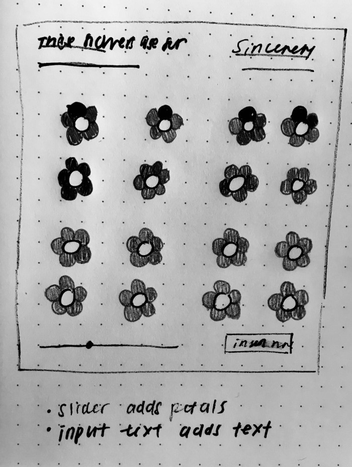
I first drew up this rough sketch of what I was hoping to do. The idea that I was hoping to achieve is that the ellipse size of the petals and middle of flower (called pistil) will change when the slider is moved. I also wanted to have a text insert so that the text will display who the flowers were for.
First I created the p5 dom elements that I knew I wanted to have. Instead of a flower, I just tested with an ellipse. I also created an h1 tag and attached css style elements to it. I also created a div with a class called “hr” for horizontal ruler. Then, I attached some css styling to get the horizontal ruler and the canvas size to match.
Then I created an individual flower in function draw() first.
Then I moved the flower into it’s own js file and made it a class. Afterwards, I created an array within function setup() to create a grid of these flowers. To correlate the slider with the size of the ellipse, I put the slider.value() in the parameters set up when I push a new class “Flower” into the array called “flowers”. I also put the “bgcolor” in the new “Flower” parameters.
Originally, I had the Flower’s function show() in the draw function. However, I realized that this was not correct, because the slider was not affecting the size of the ellipse at all, nor was the flower’s ellipse pistil changing colors with the background color. But once I moved the for loop that creates the flowers from “function setup()” to “function draw()”, it worked great!
Next step was positioning the buttons and sliders and text inputs in a more visually appealing way by spacing it out better.
Also, another issue I ran into was that the pistil ellipse was scaling with the slider but the petal ellipses were not. As a possible solution I tried to create a second slider.value() called “slider.value2()” just for the petals. I put that variable in all constructor parameters but it doesn’t work properly still. The issue is that it will scale up only once the first time it is move, but it doesn’t scale down. i tried console logging the slider.value2() and the console reads that the slider is being moved, but for some reason it won’t scale down. I am currently trying to troubleshoot this still. Update coming soon.
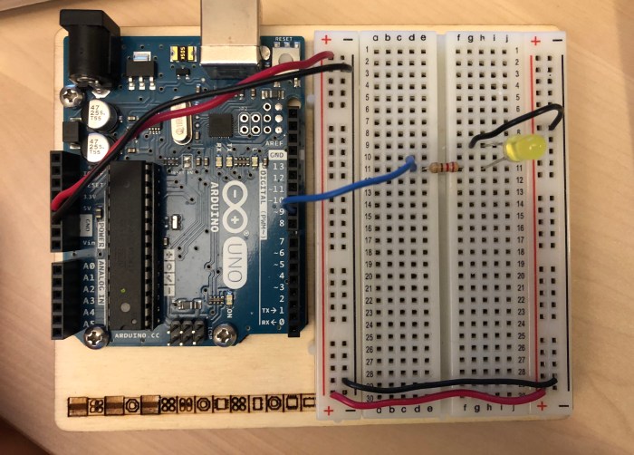
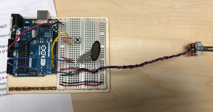
1.) First, I hooked up the potentiometer on the breadboard to the Analog Input pin on the Arduino.
2.) Followed along with the video to install the “p5.serialcontrol” App and download the “p5.js serialport library”. Then added the library to the p5.js sketch.
3.) Added the code in p5.js to first give me a list of the ports. Then I added the rest of the serial events to make sure to see in the console if the serial port is open/closed, to see what port I am working in. I then added in the variable “inData” and edited the “serialEvent()” function so that the “inData” variable reads the sensor value. Then I added in the text to print the sensor value on the canvas. See the video that shows the result of this.
4.) Then I drew a graph using sensor values. Below is a video that shows the results.
5.) Reading Serial Data as a String notes: so before this step, p5js was not reading the ASCII encoded numeric string, it was reading each individual ASCII number and applying that individual number to it’s associated ASCII number. So when we write Serial.println(), there will by 5 numbers that show up (3 numbers for each of the numbers in the string, and 2 for the return carriage and new line). So the code was in “function serial Event()” is changed to be “inData = serial.readLine()” to read the full ASCII string as a string.
6.) But then this created gaps, and in the p5 console there were “”. To solve for the gaps and “”, it was necessary to add a code that makes sure that what we are reading is a #. Below is a video that shows the result of that.
7.) The video below shows the final result without the arduino mapping the 0-255 and 0-1023, but able to give an ASCII encoded number in the p5js sketch.
—
Questions:
1.) Is the “Number” a built-in function that turns a string into a numeric, such as in the example “inData = Number(inString);”?
2.) It was helpful to watch serial from Arduino to p5.js video before beginning the lab. A question I had after watching the video, is about the properties for the functions code written in the library script. What exactly is the code doing to get it to perform that function?
3.) When does node.js come into this process? After doing the lab I was still not sure what it’s purpose is in the communication between serial port, the microprocessor, and the browser. I don’t think it was used in the lab (aside from installing it) or did I miss something?
1.) I used 2 analog inputs sensors: a force sensing resistor and a potentiometer. I hooked up the Arduino accordingly, using a 1 kΩ resistor to connect to GND for the force sensing resistor.
2.) Then, I ran a sketch with that has a “Serial.print(SensorValue)” statement in the code. Below is a video that shows both sensor values are being read properly in the Arduino’s serial port.
3.) When using the terminal as a Serial port, I added a while loop because otherwise the terminal wouldn’t stop running the values of the sensors. (This was before I was able to get the ctrl-A ctrl-\ to work). Below is the updated code:
int x=0;
void setup() {
Serial.begin(9600);
}
void loop() {
while(x<20){
// read the sensor:
int sensorValue = analogRead(A0);
// divide by 4 to reduce the range to 0-255:
sensorValue = sensorValue / 4;
// send it:
Serial.print(sensorValue);
Serial.print(“,”);
// read another sensor:
int sensorValue2 = analogRead(A1);
//divide by 4 to reduce the range to 0-255:
sensorValue2 = sensorValue2/4;
//send it:
Serial.println(sensorValue2);
x++;
}
}
4.) I printed “Serial.println(analogValue)” to recieve the ASCII value from the serial port. Below is a video of the values reading as ASCII.
Note to self: Arduino’s serial port, no matter what will alway sprint ASCII. “Serial.print()” reads everything as ASCII encoded.
5.) I then wrote “Serial.write()” in the sketch, and received the garbage characters (as the text predicted). “Serial.write()” speaks in binary but the serial port think in ASCII, which is why we receiving the binary values in ASCII form. Below is a video example of “Serial.write()” sketch.
6.) Then I tried to send the data in multiple formats. Below is a video of that.
7.) Wrote a program that reads the 2 analog sensors, following the format of the code given in the lab. I had a hard time trying to get the commas in the right place, but eventually realized that the “Serial.print(“,”)” could be placed outside of the else() statement. I wrote this code before realizing that there was a solution already in the article. Below is the code that I came up with:
for (int thisSensor = 0; thisSensor < 2; thisSensor++) {
int sensorValue = analogRead(thisSensor);
Serial.print(sensorValue);
Serial.print(“,”);
// if you’re on the last sensor value, end with a println()
// otherwise, print a comma
if (thisSensor == 1) {
Serial.println(pushButton, BIN);
}
}
}”
Sharing video of the serial port as well.
Questions:
1.) When typed the less command into the mac terminal, I got an error:
“/dev/cu.usbmodem1421 is not a regular file (use -f to see it)” Why?
2.) Tried to follow along with the “Using the Command Line for Duplex Communication.” I typed in the “screen /dev/cu.usbmodem-1421” and “control-A control-\” but it kept telling me it “Sorry could not find a PTY.”
*** Update: By checking this forum made it work by typing in “screen /dev/tty.usbmodem1421 9600″ instead of “screen /dev/cu.usbmodem-1421”
*** Update: also realized “control-A control-\” means actually using the key “ctrl” not typing in “control.”
3.) What is the difference between a “carriage return” and a “new line”? What does the “carriage return” mean?
4.) “For the handshaking it was mentioned that asynchronous serial communications could run into the problem that the sender could send faster the receiver. As a result, the receiver program slows down as the serial buffer fills up.” I am confused about this, because both the sender and receiver agreed upon the baud rate. So why is one faster than the other? Why do you need flow control?
5.) For handshaking portion, what changes the value of “Serial.available()” and makes it bigger than one? How is related to the “send” button? Is it related to the “send” button? Can we go over “Serial.available()” and “Serial.read()” more?
6.) Still not able to get Cool Terms to work, (note to self) will need to check in with someone/ resident about this.
Serial Communication Notes (for personal reference):
Electrical agreement between laptop and Arduino needs to have:
Voltage level
Speed (Ex: 9600 bps; needs to know how frequently to sample)
Logic (what do the pulses of high and low mean) The laptop and Arduino need to agree on whether the binary representation is inverted or non-inverted
When 2 programs are communicating serially, they aren’t reading each other’s programs, instead they are only reading each other’s logic. So, it’s important that they are using the same communications protocol: what the bytes being sent mean and what order they are being sent.
Questions:
So the Arduino includes a USB with a CDC that supports the asynchronous serial communication, which is what allows there to be a serial port when we plug it into our laptops. Is this correct? Is it the CDC that converts then sends the data to the laptop and serial? Just want to be sure if the CDC is considered to be a USB-to-serial converter.
—
Interpreting Serial Data Notes & Serial 4 (Devices & Bytes) Video
Notes:
Serial Data is passed byte by byte from one device to another.
Only 1 program on your computer can control your serial at a time. Ex: Coolterms and Arduino can’t both have their serial data open.
You need punctuation bytes if you have 2 or more sensor readings
Questions:
Does this mean that all the values we read in the Arduino’s serial port is ASCII values, and we always have to translate it to a decimal.
Duplex Serial Lab is showing “Nothing Found”. Should we be trying this lab out?
This week’s project is to create a sketch in an object-oriented fashion.
Here are the steps to take for this project:
1. Make one single object with just variables.
2. Put one or more functions in the object.
3. Try manually making two objects.
4. Duplicate the object using an array and make as many as you like!
—
After doing the quiz and watching the code train videos over again, I’m feeling a little more comfortable with the new syntax and concepts. So, I’m going to start on the assignment! I stumbled across some beautiful inspirational graphics this weeks that I wanted to recreate in object-oriented code and make interactive.
Below are the screenshots of the 2 inspirational images I found online and that I will try to make my own interactive version of.
grid of circles with rotating radius lines
grid of rectangles with varying lines
The idea for the left is to create a grid of circles with rotating lines revolving around the center. More lines can be created by clicking within the circle. When mouse is dragged the speed of the lines will increase.
The idea for the right is to create a grid of rectangles with moving lines of different stroke thicknesses. When you click in a rectangle, a new line will appear in that rectangle. When mouse is dragged the line thickness will change
—
Okay! There seems like a lot of parts to this series, and I’m not sure how it’ll come together, but I’m excited to start working on this piece by piece and learn a lot via practice!
Idea 1:
a.) Wrote/sketched out a plan for myself as a way to help me understand the specifics steps to tackle and what order to do them in.
b.) First, let’s do the rotating radius within one circle. For some reason, I set the variables of the radius to be half the diameter, but it was still going a little over the circle amount. So, I had to make the radius= d/2.8 in order for the line to fit the circle exactly. *Strange! why is it that I had to make it d/2.8 and not d/2 to get the radius? After creating one rotating line, I made a for loop to create multiple rotating lines. This works but I am now wondering, should I be making an array for the rotating lines? *What is a good indication of when to use a for loop and an array?
c.) Next step is to make this circle + rotating lines into a class/object with constructor. This required me to go back to the tutorials / in-class code. Eventually I got where I needed to be and was able to create a class and put it in it’s own file. Instead of separating out the functions to be move() and show(), I found that it made more sense (for me) to create a class for the circle and a function for the lines. I also decided to call the object a “clock” (even though it’s not actually functioning like one) and the other “hands”. I also decided to create 2 clocks just to try and pass different parameters into the argument.
d.) Next is to make the interactive function of adding a rotating line in the circle when the mouse is clicked on that circle. I created a function within the clock class that determines if the distance between the mouse and the center of the circle is less than the radius, then call it true otherwise false. I then created the function mousePressed() in the draw to indicate when the mouse is Pressed and when the mouse is on the circle. It was hard to get the line to be added, so I first had the code do “console.log(“clicked!”)” to make sure the code was at least working.
I’m really struggling to get a ‘hand’ to be added when mouse is clicked! I’m trying “push.Hand()’ and have made an array for the hands, but I’m not sure why it’s still not working.
After trying many different solutions, I reached out to wonderful resident Alejandro Ortiz for some help, and realized what I had done wrong. I was trying to push a new line into mouse clicked by using the same function that I used to create the rotating hands in the circle. What he helped me realize is that I should’ve made another function and variable for adding in the new line, and make an array for specifically the new hand. Then push the new hand into the array by writing a for loop in the draw() and the ‘push.handR()’ in the mousePressed().
e.) Struggling to create a grid of these circles using an array function. I thought it would be easy, but it’s unlike the tutorial videos. It is not just placing circles in random locations. My technique of trying to repurpose the Coding Train array codes for this project is not working out. I’ve decided to make a separate sketch that just creates a grid of circles using array, then I’ll try to apply that to my clock sketch. Here’s the test code for that using an example from “Make:Getting Started with p5.js.” After a while of messing with the above test sketch I decided to switch gears, and google to see if there’s any one else who has done this. I found this coding train video and am hoping it will solve my problem!
That making a 2d array video was helpful, I followed along and ended up with this code: https://editor.p5js.org/elinsterz/sketches/r1XzlU0cX which is similar to what I’m hoping to achieve. So now, I’ll try and apply the concepts in this tutorial code to my own.
f.) Okay, so went to the ICM help session, and figured out with the help of amazing resident Jasmine Soltani how to tackle creating a grid using arrays and nested for loops. I realized I was on the right track with using that 2d array technique from the coding train tutorial. The only thing is I didn’t need to make a function for the 2d array. It was just a matter of making 2 for loops with an array to achieve the grid. This worked great, and the code now looks like this: https://editor.p5js.org/elinsterz/sketches/SJ02W3R9X
However, I’m not understanding why the code breaks every time I click it once. See video below:
g.) Next step, is now to get the code to not break every time I add a new line to a circle. We figured out why it was not able to read the code after clicking into the circle just once. It was because it was adding a number to the array index and the function wasn’t able to read this new, larger number. In order to accommodate for this we decided not to have the interactive function be to add an extra line. Instead when mouse is clicked it changes the speed and angle to a random amount between 2 variables when you click in a circle. This step took a lot of console.log -ing. Code here: https://editor.p5js.org/elinsterz/sketches/B1ICMR0cm
h.) Lastly, I made some last minute style changes: the light gray was too subtle so I made it b&w, I decided to have 5 instead of 3 lines. This is the end code without all the commented out code for troubleshooting purposes: https://editor.p5js.org/elinsterz/sketches/B1ICMR0cm
Here is the final piece:
Last thoughts: I do think I got stuck WAY too much when I tried to create a grid with arrays, although I do think that I am better understanding classes and constructor (and can say that I figured out how to organize that part myself). This was both good and bad I think. Good – I learned a lot just from seeing how Jasmine troubleshoots (printing in console and narrowing down why a line isn’t working, even counting out the math in a loop). With arrays, I realized I still feel uncomfortable using it. Bad – I relied too much on the problem solving skills of other people, and didn’t come up with my own solutions. I think I still need to practice how to troubleshoot better. I’m happy that I have one more sketch to try, because this time around I don’t want to resort to asking for resident’s help. Hopefully, with this first sketch as practice, I will be able to better approach and better solve any issues.
—
Idea 2: Work in progress (aiming to be ready by Tuesday Morning)
a.) First things first, wrote a list of items to tackle for this sketch. See list below:
b.) This idea also reminded me of the quiz from a previous week with the vertical rectangles. So, instead of making the moving stripes first, I started by creating the for loop for the grid first. Here is the result: https://editor.p5js.org/elinsterz/sketches/SkZJMJMsQ
c.) Then, I moved onto the moving stripes within one vertical rectangle. By complete luck, I saw Shiffman’s code in the “Objects and Arrays” section. Having this as a reference was incredibly helpful. Although before stumbling across it, I did try to write a class for the stripes from scratch. In the end, I managed to rework the code to have it fit my sketch. Here is the sketch for that part: https://editor.p5js.org/elinsterz/sketches/HJzSC4zo7
d.) Struggling to have the moving stripes be in a grid, because the stripes are already in an array. What I think I need to achieve is to create an array (or for loop?) for the stripes array to live in. Right now, I just have a for loop() for the grid of rectangles, but I need to get the column of stripes into this grid. I’ve been trying different methods, such as making an array with a class, but I’m not getting it right. Video below and code here: https://editor.p5js.org/elinsterz/sketches/HJy_9szi7
e.) After trying out multiple things, I realized what I needed was the 2d array of processing. There needed to be another variable to move the x position of the moving stripes class. Once I did that I was able to create 10 independent columns of the class. Another time, I will try to add an interactive function but for now this is what I have.
Final code is here: https://editor.p5js.org/elinsterz/sketches/H1Irt0MiX
Below is a video of the result:
—
Reflection:
For some reason this week’s topics were much harder for me to grasp.I don’t know why this week feels different and why I was not getting it faster. Personally, I thought we were introduced with so many new terms (i.e. return, intersects, push, class, this.) that I just have a hard time remembering where to put what and when to use what. Even though I used arrays in my homework, I still have many questions and uncertainties regarding arrays. However, I’m very happy that we are learning how to organize our code in more systematic ways!
Thank goodness for the ICM help sessions, for the resident office hours, and for an extra week to soak up the information. Of all the weeks since we started, this was the one that I made the most use of the ITP community and residents. Also, very thankful for the quizzes. They really help me realize if I’m getting the content or not, and I learn a lot through the process of trying to answer them.
The concepts make sense (as in, when I read the code it is somewhat understandable), but the hard part is actually when I start to write my own code and try to apply these new concepts. I need to keep re-watching these videos, read more of the book, look at all the github example codes, go to more help sessions. I don’t want to be stuck and I would like to be a better troubleshooter; just have to push through and hopefully at some point I’ll find myself writing code from scratch and not having to constantly look at other code for reference.
For our after effects project, our group (Shivani, Shiyu, and I) cycled through many different ideas before landing on what story we wanted to tell. We had a lot of inspiration that we shared amongst each other, but below are the two main influences that shaped our project.
We also really enjoyed the concept of seeing a story unfold within a building as a voyeur.
We then worked on narrowing down the concept and storyboarding the EXACT scenes that we had to create. It was very helpful to do this step since it helped save us a lot of guess work. It was really fun to draw the storyboard based on the ideas that our group came up with. See the below images for the full storyboard sketches.
This slideshow requires JavaScript.
After we storyboarded, I drew those exact compositions in Photoshop. I made sure to keep organized with the file naming and group files within Photoshop so that it would be easy to animate once we were in After Effect. I think being organized really helped, because there are so many assets in just one scene. Screenshots below show the photoshop file with all the folders and file names.
We then got to work on animating. It was such a great learning experience to work on all the scenes with the cat! Before this class, I was always unsure of how the layer situation worked when you imported files and assets into After effects. Working on this project helped me realized how that system worked and how precomposing is done in After Effects. It was also fun to try out new skills that were taught in class (i.e. masking tool, puppet tool, some fun AE effects). Below is an image that shows the many layers within layers there were in After Effects; all the compositions were nested within each other (i.e. the file path for one scene became “Comp1< cat multiple angles closeup < only speech bubble 3 < only speech bubble 2 < man woman icon.”)
Shivani then put together all the comps in Premiere and integrated the soundtrack that Nick made. The final touches of the end credit sequence and title intro were created.
—
This project and class helped clarify a lot of AE tools that I never fully understood before. I’m definitely going to animate more now that I have a better (though probably still very shallow) understanding of how this program functions!