Most updated version before user testing on 12/05/18:

—
Process:
As a way to help me with the many to do items, I have a breakdown of lists that I need to tackle everyday to help me stay on target.
The sheet can also be seen here: https://docs.google.com/spreadsheets/d/1zA4OJrYoYLFRfl6XcdlWMDRCV-Dq8sbgWobO5o2G_kc/edit#gid=1107503517

As shown in the sheet above, there have been different items tackled over the course of a few days, therefore it is hard to pin point chronologically what I started working on. I will try my best to organize and explain the activities that happened throughout the week, though they may not be in order.
a.) Almost immediately after last week’s class, I worked on the light sources for both the house and the “sun” lamp. The full documentation for the light source can be seen in this separate blog post: https://emilylinprocess.blog/2018/11/30/fab-wk-4-enclosures/
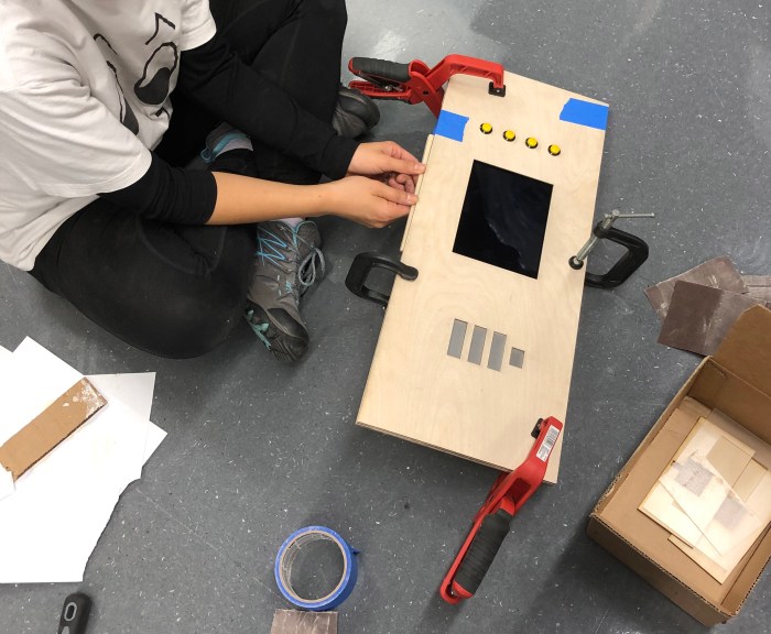
b.) I also worked on the front panel, which has many components to consider: the 4 buttons, the battery symbol (with the LEDs in the back), the iPad screen display. For this part, I first started out by measuring out dimensions I needed and sketching out the plans.
There would be four 1/8″ wood pieces that would have a top layer, 2 layers in the middle that would hold the ipad, and a bottom layer. This would act similarly to the halloween midterm crystal ball box – there would be an open slit at the bottom of the front panel that would act like a drawer opening. See sketches below for details.
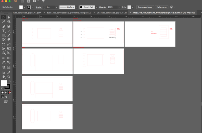
Illustrator file for laser cutting was prepared:
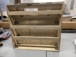
Cardboard prototype was assembled after laser cutting:
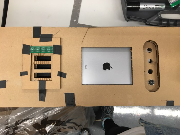
back of front panel


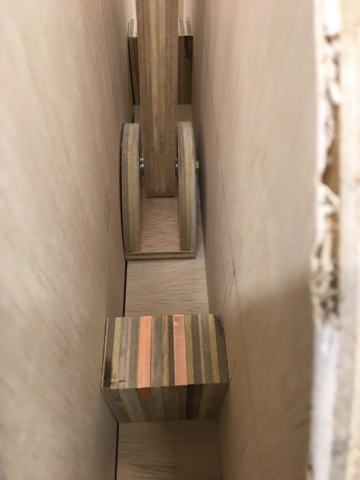
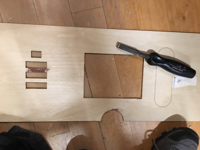
Then the 1/8″ wood was used for the final. This proved to be very difficult because the laser cutters are extremely slow right now. They must be overused. Anyways, to save time I had to chisel out some parts because the lasers weren’t cutting through.
Below is the fully functioning ipad drawer. Because I was in a rush there are some issues with it, such as the fact that I forgot a space for the ipad charger. Also it didn’t take into account the safari url bar at the top.
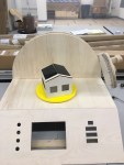
c.) Light in the house
First was trying the led strips. Next was the led lamps. These are not the right type of white light (too cool), but they are easier to do gradual changes and they require less volts. I tried to change it using reflective yellow acrylic, but that didn’t look good.
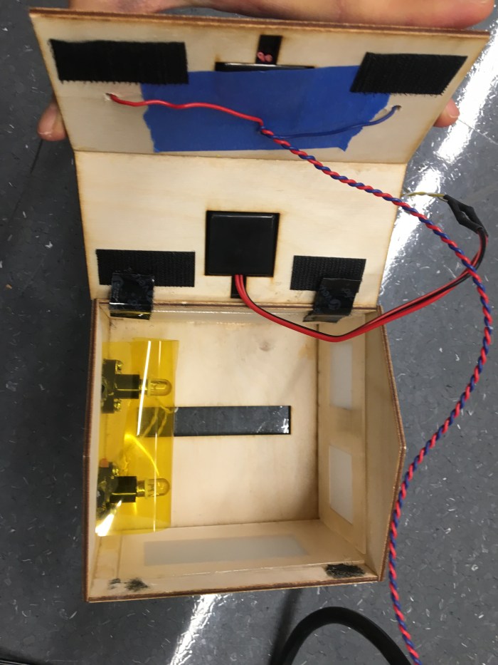
d.) Piecing it all together: soldering the wires to the led lamps, adding the copper tapes at the end, adding the buttons, troubleshooting the p5js sketch.


e.) Here is my circuit drawing and also a photo of the wiring of the circuit. Will aim to get a fritzing version soon.
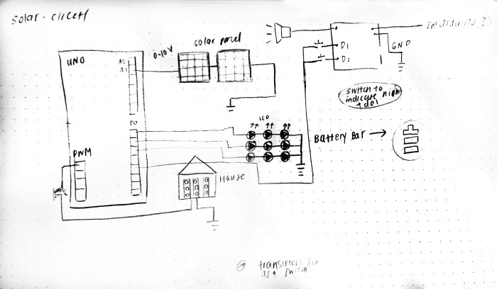

Below is an image of how the arduino is hooking up to the house and solar panels.


f.) Here is the code for Arudino:
”
//pin numbers for PWM of house LEDs
const int HouseLED1 = 3;
const int HouseLED2 = 5;
const int HouseLED3 = 6;
void setup() {
Serial.begin(9600);
pinMode(HouseLED1,OUTPUT);
pinMode(HouseLED2,OUTPUT);
}
void loop() {
int solar1 = analogRead(A0);
int solar2 = analogRead(A1);
int solarAvg = (solar1 + solar2)/2;
int mapSolar = map (solarAvg, 650, 1023, 1, 255);
Serial.write(mapSolar); // binary sent to the computer
// Here you can add more lines for each condition in order to light up more LEDs in the house.
if (solarAvg < 600) {
analogWrite(HouseLED1, 0);
analogWrite(HouseLED2, 0);}
if (solarAvg >= 600 && solarAvg < 780) {
analogWrite(HouseLED1, 50);
analogWrite(HouseLED2, 50);}
if (solarAvg >= 780 && solarAvg < 900) {
analogWrite(HouseLED1, 40);
analogWrite(HouseLED2, 40);}
if (solarAvg >= 920 && solarAvg < 980) {
analogWrite(HouseLED1, 100);
analogWrite(HouseLED2, 100);}
if (solarAvg >= 980) {
analogWrite(HouseLED1, 254);
analogWrite(HouseLED2, 254);}
}”
***
Here is the code to read the analog input through the serial connecter. Repurposed from a previous pcomp/ icm sketch that was done.
”
let serial;
let portName = ‘/dev/cu.usbmodem1411’;
let inData; // for incoming serial data
let xPos = 0;
function setup() {
serial = new p5.SerialPort();
serial.on(‘list’, printList);
serial.on(‘connected’, serverConnected); // callback for connecting to the server
serial.on(‘open’, portOpen); // callback for the port opening
serial.on(‘data’, serialEvent); // callback for when new data arrives
serial.on(‘error’, serialError); // callback for errors
serial.on(‘close’, portClose); // callback for the port closing
serial.open(portName); // open a serial port
createCanvas(1024,768);
background(255,255,0);
}
function draw() {
// fill(255);
// textSize(60);
// text(“sensor value: ” + inData, 20,100);
graphData(inData);
}
// get the list of ports:
function printList(portList) {
// portList is an array of serial port names
for (var i = 0; i < portList.length; i++) {
// Display the list the console:
print(i + ” ” + portList[i]);
}
}
function serverConnected() {
print(‘connected to server.’);
}
function portOpen() {
print(‘the serial port opened.’)
}
function serialEvent() {
inData = Number(serial.read());
}
function serialError(err) {
print(‘Something went wrong with the serial port. ‘ + err);
}
function portClose() {
print(‘The serial port closed.’);
}
function graphData(newData) {
// map the range of the input to the window height:
var yPos = map(newData, 120, 255, 0, height);
// draw the line in a pretty color:
stroke(0, 100, 255);
strokeWeight(5);
strokeCap(SQUARE);
line(xPos, height, xPos, height – yPos);
// at the edge of the screen, go back to the beginning:
if (xPos >= width) {
xPos = 0;
// clear the screen by resetting the background:
background(255, 255, 0);
} else {
// increment the horizontal position for the next reading:
xPos= xPos + 2;
}
}”
g.) The copper tape / switches: I was able to add the copper switches but I’m still trying to program it so that each switch will turn off the light and show a new screen on the start and end points. Will come soon. Below are some images of the copper tape and plate ready to go.