Despite this being the last week of finals and the fact that I’m with a cold, I was super excited to do something with servo motors. I was a little bit more short on time than usual, so I wasn’t able to start till Thursday. I’ve been wanting to make something/ play with servo motors all semester long, and I finally found a good chance to do so. However, I still wasn’t sure what I wanted to do with servo motors so I scavenged the net for some good inspiration on servo projects. I found great examples on the “Make:” site, but eventually stumbled upon this great resource from the site etechnofiles.com: https://etechnophiles.com/top-10-arduino-projects-beginners-2018-honest-opinion/
I really liked project number 8 “Servo motor control with Joystick” and decided I would do a follow along with their tutorial: https://www.youtube.com/watch?v=kA_pbMR6jVs
This was also helpful: https://www.hackster.io/darwindelacruz/how-to-control-single-servo-motor-by-joystick-c57395
Also, remembered the “Mood Cue” project from the “Arduino Uno” book. I was inspired to do my own version that uses icons instead of words and uses a joystick as well!
—
a.) Inspiration: I saw this great kid’s product online from Counterprint Books studio. I love the design and wanted to somewhat emulate the visual aesthetic of it.

b.) Sketch Idea + Make Measurements:


c.) Prep Illustrator Files Based on Measurements

d.) Make Graphics


e.) Set up Arduino + Breadboard (based off videos mentioned above + Arduino Uno book)

Game Change! Motor Mount for Dice Wheel Box!
So because I am sick, I’ve accidentally slept in (which really rarely happens) the morning of class and did not have time to execute my above mood idea 😦
I really tried though, even thought I slept in I still tried to got to canal plastics and laser cut the piece. Unfortunately, as I don’t think the laser cutters are doing too well. Because I cut 3 times on the acrylic and the hole cutouts still didn’t go through. See image below for proof that the acrylic wasn’t working out to my favor.


To be realistic with time, I decided to change gears (you get it?!) and work on creating a nice mount for my previous project I did for pcomp. I did this project in week 4/5 of this semester, before fabrication. See previous post for it: https://emilylinprocess.blog/2018/10/02/pcm-wk-4-project/
Therefore, my motor was mounted pretty poorly. I just mounted it with very strong tape. See below.
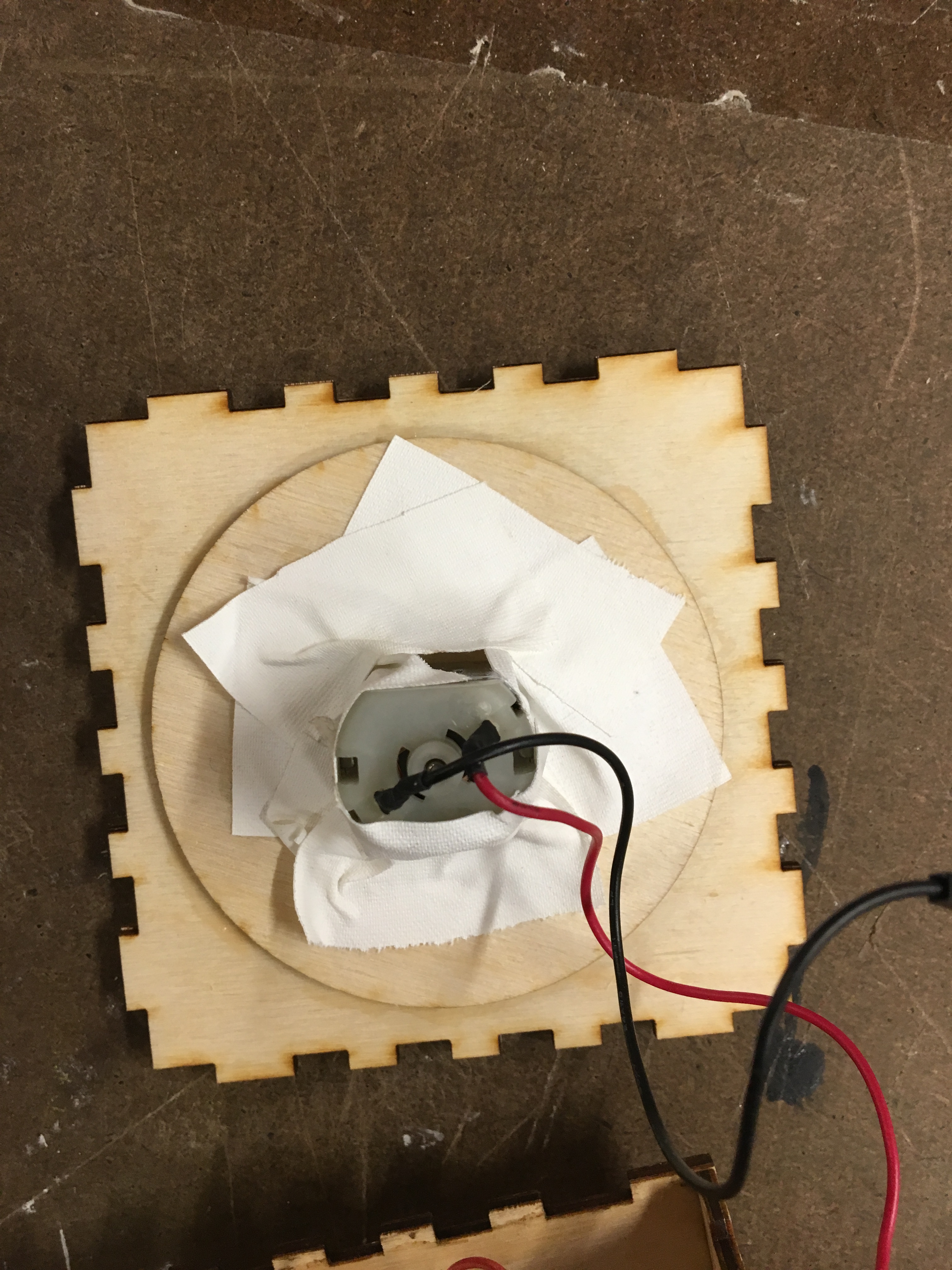
So I decided I would make a nice mount to hold the motor in place. I used the caliper to get measurements of the motor.

Then I sketched out the measurements and the shape I wanted for the mount. I also drew it on illustrator.


Laser cut this mount. The dc motor fit well in the mount, but the mount itself was slightly too large for the box itself. Therefore, I needed to use the band saw to cut off just 1/8″ off on each end of the motor mount acrylic.


After doing that, I was able to fit the mount nicely in the box and it all fit so well I didn’t need to glue it to the box like I thought I would need to! So this mount needed no glue at all!

I also realized after doing this mount, that when I first done this for pcomp I had purposely left out one side because I needed to get access to the arduino. Therefore, one side does not have a face! I decided to go back into my previous illustrator file for laser cutting this piece and make the missing face but with the hole for the wires to go out of the box.
Then I glued the top piece, because now that I have the missing side, I could finally glue it down.

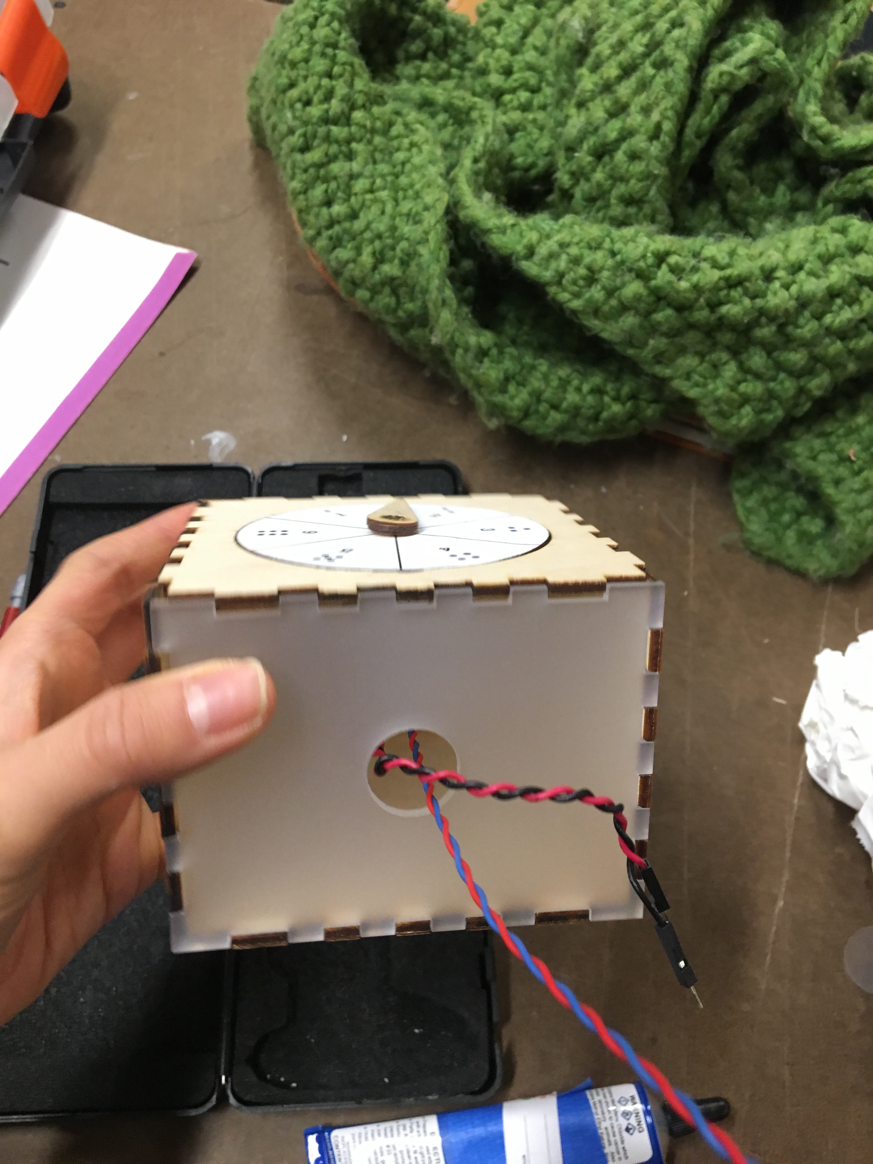
Here is the final result! This uses the code and breadboard set up from before.

