Lab: Setting up a Breadboard
I followed along the three examples to find out if the LED would light up. I tried to guess first, but before checking the answer I tried to set the circuit it up myself. Below are 3 examples.
Answer 1:
Answer 2 (the one that doesn’t light up):

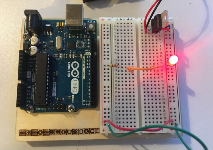
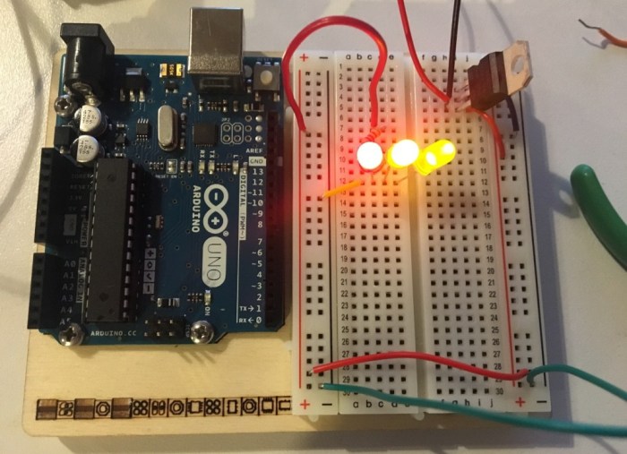
Answer 3 (the one with the LEDs in parallel):
As a test for myself, I tried to set a circuit up with the LEDs in series, instead of in parallel. Below is the result:

This was a very helpful lab for familiarizing myself with the concepts we have been reading about. It was a great hands on experience in setting up the breadboard and trying to get the jumpers to connect properly.
After finishing, I read the note about trying to have the colors be as consistent as possible. I think that I did not do a great job at color consistency in this lab, but moving forward I will definitely need to be more organized about making sure that the green/black = ground; red = power; white/blue = data.
Lab: Electronics – Using the Multimeter
Measuring Voltage
1.) As shown in the reading, I used the 5V output from an Arduino and added an LED and a 220-ohm resistor to the breadboard. Next, I measured the voltage between the power and ground bus rows on the breadboard. It took me a while to get the multimeter to not jump around and stay on a number, but eventually it showed a consistent range between 4.5 – 4.8V. (Video below)
2.) Next I measured the voltage drop across the LED by putting the leads in parallel with the LED. The reason that the voltage drop is the same when I put it in parallel is because the voltage in parallel is not split (like it would for amperage). Below is a short video of this process.
Switched LED Circuit
1.) Wired up the circuit to include the switch before the resistor and LED. It is great to keep in mind that LEDs usually consume 2.0-2.6 volts (V) and 20 miliamps (mA).
I measured the voltage of the resistor = 2.8 volts
voltage of the LED = 2.03 volts
total voltage between power and ground = 4.82 volts
The voltage of the LED + Resistor is around the same amount as the voltage of the total circuit.
Adding up Voltage
Next, I measured the voltage across a circuit that has 2 LEDs in circuit. The result was almost accurate, but I was off by 0.37 volts. Here are the measurements:
– LED1 : 1.73 volts
– LED2 : 1.93 volts
– Resistor: 1.07 volts
– Total voltage between power and ground (when measured): 5 volts
– Total voltage between power and ground (when calculated): 4.73 volts
Components in Parallel Measuring Current

I measured the current through 3 LEDs that were in parallel. The circuit was completed when I put one lead in the ground and the other in parallel with the LED’s cathode. The measurement of the current was: 4.47 mA
Generating a Variable Voltage with a Potentiometer

I measured the voltage between the center position and ground with the potentiometer added to the circuit. I noticed that the multimeter number changes as I turned the knob.
—-
Questions:
1.) I tried measuring the resistance of a diode, but the number started high from 10MΩ and continued to decrease; however, the number did not “flash briefly on the meter, then disappear” as described. Is that okay? When is it important or needed to check the forward bias of the diode?
2.) I put the LED in reverse to try and measure the negative voltage, but the multimeter didn’t show any negative number for the voltage. Why?
3.) Why is there a “Warning: Measuring amperage with the red probe in the voltage hole when you have no idea how big the current is, or measuring voltage with it in the amperage holes is a good way to damage the meter.”? I think I need more clarification about how to measure the amperage through the LEDs in the circuit.
