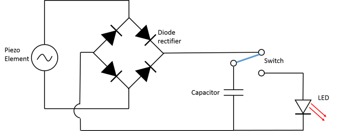
Before realizing that we needed to power the led with either a magnet and coil or a dc motor, I looked into a couple of other different ways to power the led with kinetic energy. One of the more intriguing ideas I stumbled upon was the piezoelectric. I found this schematic online that I found extremely helpful even when I changed over to using a dc motor instead. This schematic (found from teachengineering.org) had all the components I was looking for: diode for back voltage, capacitor for storage, switch and the led.
To make this work for the dc motor, I changed the diode rectifier in the circuit to a single diode. Below is the adjusted schematic.
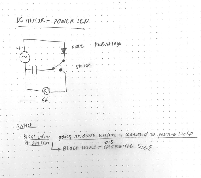
The kinetic energy is converted into electric energy by the dc motor. This energy is stored in the capacitor. The diode is added to the circuit to prevent the capacitor discharging into the motor. When the switch is turned on the energy in the capacitor is released into the LED. The amount of voltage needed to power this LED is ~2.5 – 3.
Below is the circuit that uses the multimeter to find the amount of voltage stored in the capacitor as I spin the motor.

One of the main troubleshooting issues was not knowing how much voltage to charge it up. It also took a while to figure out this circuit.
Below is the video that shows me hand spinning the motor till it reached 2.58V. After it reached 2.58V I turned the switch to charge the LED.
