Final:

Final code: here
Final interaction:
1. if key is on handle: fade light on, play on melody
2. if key is not on handle: turn light off immediately, play off melody
3. if key is on handle, but room is dark: turn off light
—
Process:
This has been a bumpier week with sensors and the Arduino boards. My Arduino uno stopped working for some reason, so I switched over to the Mega. I then realized the Mega was too big for my sconce enclosure so I then switched over to the Uno.
I also changed between 3 different type of sensors (and at some point even tried copper plates/tape) before finally sticking with the force sensing resistor. I switched around so much because I realized the touch sensors wouldn’t work with my wood on wood, wood on metal mechanism – it only reacts to touch. In hindsight, it is obvious that the capacitive touch sensor (both the one with the button on the sensor and the breakout version) would not work for a non-human touch. See my (sort of) step-by-step process to figure this out.
a.) First I narrowed down my light choice to be a chip on board, instead of Phillips Hue light bulb or high watt led.

b.) I tried out my circuit with a breakout capacitive touch sensor. A whole day was spent figuring this new sensor out because I needed to review the I2C information from Intro to Pcomp. There was a learning curve with this “smarter” sensor. I didn’t end up using it because I realized it doesn’t work for keys. *The capacitive touch sensor will only register as a “touch” if a person’s is holding the key.
It works with hand touch, but not with metal touch.
c.) All the while I have been fabricating the box using the CNC. See the full fabrication process in my subtraction blog post.
Photo here of the final box, sanded and waxed.

I then assembled the light fixture together. And eventually assembled all the parts. For the light fixture I ended up not using the socket I had bought because the COB was too far up in the globe. This caused only half of the fixture to be illuminated.


Switch mechanism was also assembled and full documentation can be seen in subtraction blog.

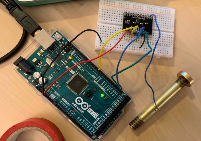
d.) After realizing that both touch sensors would work, even with the switch mechanism. I switched over to a Force Sensor Resistor. Circuit with that below.

After finalizing the circuit, I soldered it.


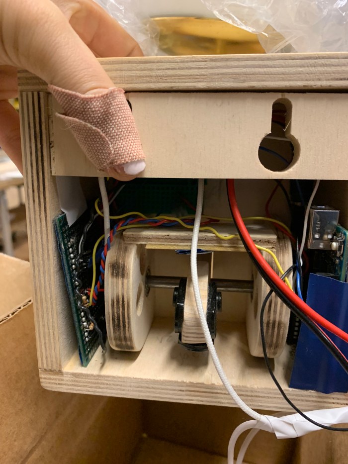
e.) I then put all the parts together: mechanical key hook switch, the pcb, the arduino. From doing this I realized how little space I had in the enclosure. The force sensor is a difficult sensor to fix properly and solder other wires to. I ended up giving it it’s own breadboard close to the switch so the little pins it has doesn’t constantly fall off.

f.) The dc adapter also had to be cut and soldered for multiple reasons. One of them being I wanted to use the white wire so that when it hangs on my white wall, it would not be too noticeable. Secondly, I didn’t want my arudino usb connected to my laptop. So, there needed to be a way to charge both the arduino and the 12V light with the adapter.
The power of the adapter was cut and connected to both the power of the dc jack plug and the power of the COB.


g.) Last thing was putting it all together and adding the back panel for the hooks.
—-
Helpful resources I encountered for specifically the capacitive touch sensor portion:
b.) https://playground.arduino.cc/Main/CapacitiveSensor?from=Main.CapSense
