What a fun idea! It’s immediately attractive with it’s overload of buttons, switches, cool interfaces, but I couldn’t help but want it to do something. I do realize that doing something would defeat it’s purpose of acting as an artist statement/ sculpture rather than a functional design object. However, with all those buttons and switches I could imagine myself vigorously pressing and expecting a response from the machine, then being disappointed when I realized there would never be one. Either way, it was probably a great study on human psyche and what is appealing to us and what we expect.
Note to self: I will definitely have to check out that Leeds Radio place he mentioned!
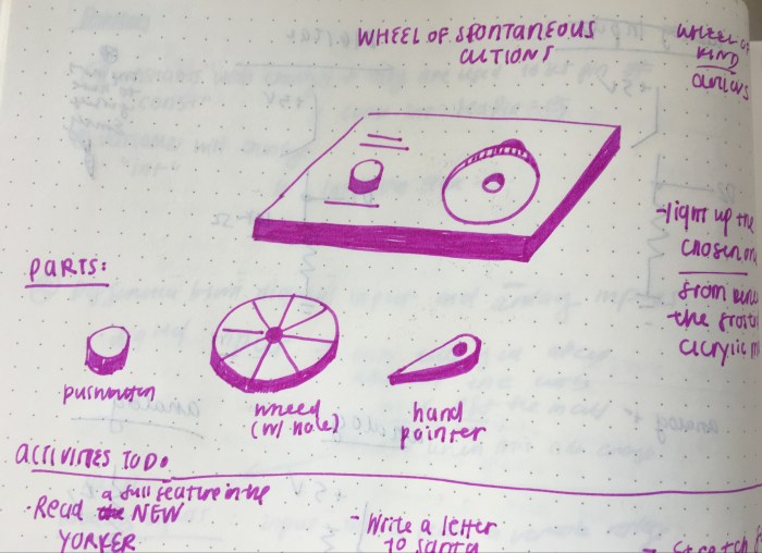
For this week’s more open ended assignment, I was excited to do something fun and interactive! I thought about a couple of ideas, but eventually landed on doing a wheel of fortune spinner. Except that instead of spinning for money, the pointer would land on a random activity that the user would have to perform (i.e. clean the toilet, buy a plant, stretch, etc). The idea is that the finger spinner would land in a different place for a different amount of time each time the button is pressed.
I drew up a few initial sketches to show what I was initially hoping to achieve (heads up: this concept does change slightly, but the idea of a finger spinner remains the same). In the first few drawings, such as the image below, it was designed to be just a flat board with the push button on the side. Included are all the separate parts that would make up my interactive piece.
sketch of initial concept
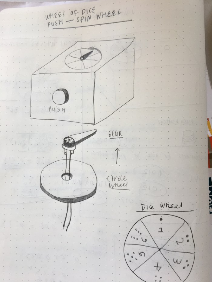
However, I realized when I was getting my assets ready to build that this flat surface would be a challenge. The motor would have to be tucked away somewhere. So, I decided to redesign the form of the interactive piece. The image below shows the updated design.
updated sketch for spin-the-wheel idea
I also updated the design so that if it were a box the push button would be in the front, as a way to save wood and space. Also, my friend went to a game night last Thursday and told me how they had an issue with throwing the dice because there was no space on the table. From this, I realized the spinner could act as a dice. For the people who have no space to throw a pair of die, they could just use this push button dice wheel. Not to mention, the updated design was a 3″x4″ box and there was no way I would be able to comfortably fit text phrases on the wheel.
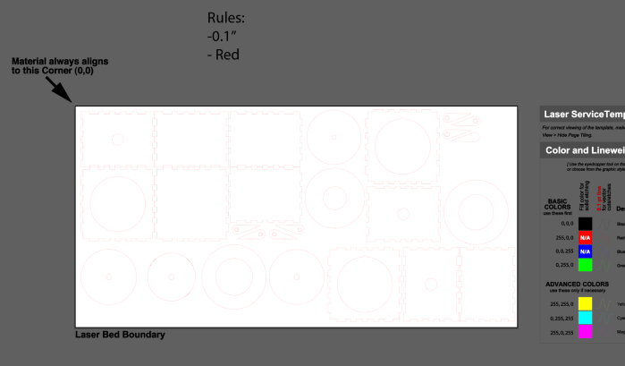
I found a teeth box design I could use online (why reinvent the wheel, right?). After downloading the online illustrator file, I opened it up and tweaked the design to include the holes for the push button, the wheel, and the finger. Below is an example image of the illustrator file with all the parts (and duplicates) for the piece.
Side note, the finger was a fun challenge. To draw the finger, I needed to have an accurate measurement of the motor’s gear. With help, I used a caliper to measure the exact diameter of the wheel’s outer and inner rim. The image below shows the calculations that helped me create the pointer with an accurate hole for the gear to fit through.
After finishing up the illustrator file I was ready to use ITP’s Laser Cutter for the first time! I first used cardboard to help me prototype and make sure my drawings were accurate. After printing, I fit the pieces together and thankfully the pieces for the box fit well. See the process photos for that below.
The only issue was with the circle piece bottom support piece for the wheel. It was too big and I needed a way to have the gear fit well into the bottom layer. So I altered the illustrator file to include a couple of new pieces that considered the gear. Then I decided it was time to laser cut on the cheap plywood! See the exciting process below (not that exciting maybe, but this is my first time!).
Now onto the last parts of the fabrication/ building aspect: assembling and soldering the push button. This part of building the box went by with little hiccups, it was a meditative and straightforward process of gluing the pieces together. See images below.
assembling the box by tape first
all the parts for the box
gluing the box
after soldering, hot glue was added
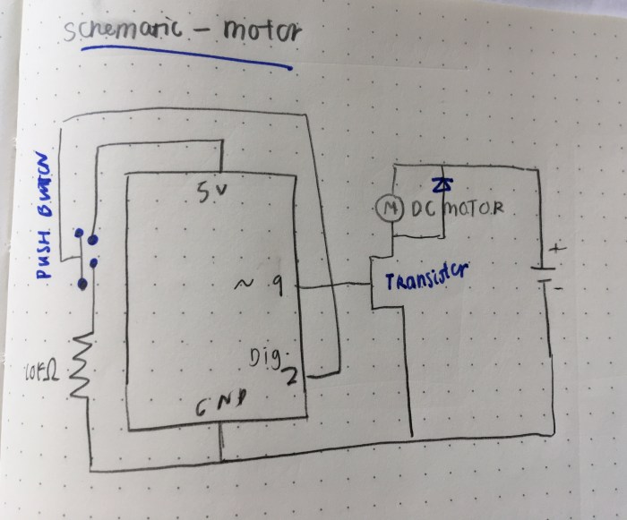
Now the final step for me was drawing the schematic, wiring up the circuit, and writing the code! I based the circuit schematic off of “Project 9: Motorized Pinwheel” of the Arduino Uno book. I forgot about this project, and had not realized there was already something so similar to the dice wheel idea. I’m so thankful for it, because there were so many parts to the circuit design that I wouldn’t have gotten right if it were not for this chapter in the book. I probably would not have added the diode ( I had no idea about the back voltage and still am not sure if I completely understand). So both the circuit drawing and the code are based off of this.
circuit drawing
image of the circuit and a video of the motor spinning when the push button is pressed.
Here is my initial code, which is taken from the Arduino Uno book.
” const int switchPin = 2;
const int motorPin = 9;
int switchState = 0;
It was very beneficial to have this project as my foundation, but I’m running into challenges with having the push button and finger interact the way I want it to. It is supposed to spin for a random amount of time when the button is pushed once. Right now it is just spinning whenever the button is pushed.
Then, I thought that maybe it had to be a analog output since I am trying to have the push button read varying times. However it didn’t work. Below is the code for that:
“const int switchPin = 2;
const int motorPin = 9;
int switchState = 0;
// if switch state is on then motor spins at random intervals of time
if (switchState == HIGH){
analogWrite(motorPin, random(100, 9600));
}
//switch state is off
else {
digitalWrite(motorPin, LOW);
}
}”
—-
After going to the professor’s office hours, Tom helped me figure out what code to write in order to get the spinner to interact the way I intended it to. I realized that I needed to set a variable for the delay length and define the variables for the delay length variable within the “void loop()” function. I also needed to add a delay between the “if ()” and “else()” statement. It was a very helpful session; it also helped me realize what I should focus on moving forward. I am specifically struggling with writing code from scratch, so I need to devote more time to improving my programming skills.
With a lot of help from Professor Tom, here is the code that tells the motor to spin at random amounts of time when the button is pressed:
“const int switchPin = 2;
const int motorPin = 9;
int switchState = 0;
int delayLength = 0;
// if switch state is high set the delay length and start the motor
if (switchState == HIGH){
delayLength = random(200, 1000);
digitalWrite(motorPin, HIGH);
Serial.println(delayLength);
delay (delayLength);
//if the switch state is low stop the motor
} else {
digitalWrite(motorPin, LOW);
}
} ”
And below is a video of the near final result. The last part is to add the dice wheel graphic.
Motor
Below is a video of my results after following along the “Analog Ouput: Motor Control“. Instead of using the wind motor, I used a motor I already had (unfortunately it doesn’t have any cool tissue or fan on it so the motion of the result is not too clear). However, I think there is an issue: I don’t think the potentiometer is adjusting anything in my circuit or in the speed of the motor. I think that the motor is running directly from the DC power converter. I’m not sure if that is right. I will work on trying to get the potentiometer connected to the motor in my next step.
—- Servo
I followed along with the “Analog Output: Servo” video and it worked! Below is a video of the result:
Code taken from the tutorial video:
“//Analog Output-Servo
//libraries give you increased functionality in your code
#include <Servo.h>
Servo myServo;
void setup() {
// attach servo to pin9
myServo.attach(9);
}
void loop() {
int sensor = analogRead(A0);
int angle = map(sensor, 0, 1023, 0, 180);
if (millis() %20 < 2) {
myServo.write(angle);
}
//delay(20);
}”
—-
Lab 5: Tone Output Using Arduino (WIP, Will be ready soon)
Below is a video that shows the checking of the sensor input range.
Play Tones Lab: I followed along with the written lab. Below is a video that shows the different frequencies change based on the analog input (photocell resistors).
Force Sensing Resistor as a Note:
I followed along with the written lab to “make a sketch that plays a note on each sensor when the sensor is above a given threshold.”
This week’s more open-ended assignment is to use functions for either a.) re-organize my code from a previous assignment or b.) start anew. I debated between the two options and decided I’d attempt to do 2 ideas, one of which is based on the previous week 2 assignment, but it will not be having the same design or interaction. Since, I made a button and not a slider or knob for last week’s assignment, I also really wanted to try to figure out those interactive elements for this week and integrate it into 1 of my 2 ideas.
Love coming up with ideas and mocking them up!! Below are some sketches of the 2 ideas I’d like to explore.
Idea 1:
This concept is based on the clock sketch from week 2. However, instead of clocks I will be using letters that rotate individually but are placed in a formation of concentric squares. This idea utilizes the same elements, such as rotating each object on its own axis (using push, pop, translate, angle). This sketch will just have a couple more parameters (i.e. the letters must loop in a square formation). The left image below is a static illustrator sketch of what I am hoping to achieve.
Idea 2:
Before moving to NY, I used to go on hikes over the weekend. During these hikes I’d take photos of the insects and fungi I’d see. I’m hoping to make a wallpaper of mushrooms. I also plan to integrate the mouseDrag() and mouseRollover() functions (that we learned from last week’s assignment) so that users can either change the scale or change the placement of the mushrooms. Below is a quick illustrator sketch of this idea.
Okay, so going to get started! Let’s aim for the best and see if I can actually execute these ideas properly in code!
—
Idea 1:
a.) I figured out last week that the coding is more manageable and less daunting when I tackle one interactive part at a time. So, I first started out with trying to get one individual letter to properly turn from it’s center. Below is the result of that.
b.) I managed to use a for loop to have a horizontal row and vertical row for the text. However, this only allowed for half of what I wanted. Also, my code got very long when I had a for loop for each of the 5 letters (reference code: https://editor.p5js.org/elinsterz/sketches/HkTsToCtX). I think there must be a more simplified code I can use.
c.) Initially, I was running into issues trying to get the “H” to loop on all four sides, but I realized my second “H” was not looping in the right place. I had miscalculated, I think. So glad that it is figured out, and I can just repeat this code for the “E, L, L, O”!
d.) Great, so now all the letters are looped into concentric squares (see below)! Next step is to add a button in the middle that changes the black background to white (and vice versa for the text) when it is clicked. I thought of this idea as I was working on the sketch, so it’s a little different from what I mocked up originally. But, I wanted to add on this extra interactive challenge for myself, since there is nothing interactive about this current rotating “hello” sketch.
6.) I started a new document to try out the inverse color button for the center “hello” text. I struggled at first to understand why it wasn’t working, because my code was doing the exact same thing that the Github “button switch” code was. Eventually, I figured out the the variables have to be in the function mousePressed() as well. I keep forgetting that each function’s variables are for that function only. I got the button to inverse the colors in the end. Now, it’s time to combine this code into the other one.
7.) I was able to combine the two codes fairly easily. Also, realized that I think it was boring having all the letters rotate at the same angle and speed. So I decided to make every other letter go in the opposite direction. I think it is more interesting this way, but maybe it’s just my personal preference (not sure which I like better).
8.) Last and easiest step… I want to change the text to a cooler font. I think I’ll try to upload a open source typeface for this one. Below is the final result with a serif typeface and lower case letters! Personally, I prefer the serif, I really am not sure why I do. Perhaps it’s because it makes this sketch feel less digital and more unexpected?
a.) First step I did was review Eva’s moon slider code from last week, to remember how she loaded in the images for the animation. Also, I reviewed this Click and Drag code from last week’s references.
b.) Next step is separating out all the mushrooms as individual svg files in Illustrator.
c.) Then, I decided to just try uploading one mushroom image before uploading them all into the folder. This was where I struggled. I had saved them all as svg files and for some reason it just wasn’t working when I did that. It kept showing up as “loading” in the canvas area, so eventually I gave up and just made them all png files. And this seemed to work (yay!). Below is an example of the working mushroom image in the editor.
c.) Next step is trying to make this one mushroom draggable, which I used the github code for. I tweaked parts of the code so that the image is the one being dragged. It worked! I also made the code that relates to “dragging” a function called “mouseDrag().” Full disclosure, I didn’t come up write the code/ think of the solution for this dragging function. I just edited it to make it work for me. Having this reference to base it off of definitely helps me better understand it though (I don’t think I would have been able to come up with it by myself unfortunately). An example of the draggable mushroom is below.
d.) Now, I’m going to try to make all the mushroom images draggable. I think I need to use the for loop to help make a nice scattering of mushrooms. I’m running into the issue of the mushrooms not being able to be draggable by itself. The two mushroom that I have are being moved at the same time. I need to troubleshoot this.
e.) So, I’m really having a hard time making each mushroom draggable by itself. I’ll be going to the help session to figure out how I can make it not all drag together. But in the meantime, I’ve loaded up and arranged the mushrooms how I’d like them to be. See example below.
f.) Added the text, but I still was not able to get each individual mushroom to be independent from the rest. I tried various solutions, such as making each mushroom it’s own function. I’ll be reaching out for help at the ICM help session, so hopefully we can solve it there. For now here is the code that drags all the mushrooms together: https://editor.p5js.org/elinsterz/sketches/rJceunk5X
g.) Went to the help session and worked with one of the residents, Jasmine, but by the end of the help session we could not come to a solution that worked. She was SO helpful but there’s still something wrong. Here is the solution we came to at the end: https://editor.p5js.org/elinsterz/sketches/rJG741ecX
We tried to tackle it one mushroom at a time instead of trying to do all 13. There’s definitely still work to be done on my own, but for now I’ve scheduled office hours with her on Wednesday to go over this code some more.
I think tonight I’ll try to troubleshoot the code again and rearrange using classes. I hope this will solve it. I’ll update this post with what happens.
—
Reflection
It is always so fun to come up with sketch ideas that I want to make come to life. The hard (yet rewarding when it works) part is usually with making it come to life. For the “hello” piece, I remember really enjoying the troubleshooting process. For this sketch, (maybe because I was more calm and working in a super quiet area) I was more methodical with trying to figure out what’s wrong. However, with the mushroom sketch, I really don’t think I was being smart about how to organize and go about fixing the problem. I was hoping to get the drag function to be applied to multiple objects, and it ended up being less simple than I expected. As usual, I need to learn to be patient and logical in order to think of smart solutions. There are tons of new code that we are learning every week so I’m so glad that we have projects that help us to retain this new information.
One of my most treasured place in Manhattan is the Bobst Library, especially it’s dead-quiet graduate student working area. It is the best place for writing and blogging, as I am doing now. This means that I need to pass by the common eating and drinking area of the basement floor in order to get to the study area. And occasionally I would give in. I can’t help myself but I somehow make my way over to the room full of NYU purple vending machines. It is a welcoming, somehow eerily futuristic semi-circle room. Even the sounds that the vending machine makes are machine-like and robotic.
In the past, I would stand for minutes in front of that machine trying deciding between the many different options. Of course, I would always want the bbq chips, but then the health-conscious side of me would gravitate towards the veggie chips and the minutes long cycle would continue in my head as I stare at the options. A couple of times, I’ve even walked away thinking I really shouldn’t be doing this. But then a couple minutes later, I’d end up right back in that room, ready to pay for a snack.
However, today, instead of being a user. I was an observer. It was fascinating to see how long other people would stay there trying to decide what to get. I thought I was just being indecisive. But it was a great revelation to see other people doing the same thing I do – stare for minutes, then either pay or leave. And in the beginning of this video below, you can even see the person deciding not to get anything after staring at this fluorescent glass box (just like I’ve done many times before).
It got me to think, why are we so indecisive in front of the machine? The moment I walked up to one, I knew why. Look at how many options we are presented with (See image below)! It reminds me of a scaled down grocery store – an aisle that’s neatly packed into a box. It’s hard to even take in the whole landscape of options. This is just information overload, and I personally think there is such a thing as having too many options.
Then this screen next to the snacks and drinks would flip through different graphics that feel corporate and cold. There’s a touch screen text at the bottom to help guide us, which makes sense, but seems a little self explanatory since there are no physical buttons. But still I appreciate it. The screens it would scroll through would be short instructions on how many different options you could pay with: by coins, by card, by dollars.
I still remember the first time I used these specific vending machines and how long it took me to understand how to pay with the card. I remember being so confused as to why nothing would happen when I kept swiping. I would keep swiping and nothing would happen. After many tries and actually switching over to another machine I realized I had been swiping the wrong way.
The way you pay with your card is an odd interaction. Vertical swiping is not your standard style of swiping these days. You usually don’t turn it on the side to swipe. And I can easily imagine people putting their cards in that main horizontal swipe slot. The side vertical is not an intuitive act for people to do, especially because usually if you are swiping vertically the top and bottom are open so the card swipes through and comes back out the other way. But for this vending machine it doesn’t do that. You need to insert the card and swipe while still having your card stuck in the slot.
Because there is barely any indication when you swipe your card if it didn’t work. The screen would not read error, or tell you to swipe your card the other way. It would simply act like it didn’t read it. That is one of it’s biggest interaction flaw, in my opinion. The fact that there is no feedback system when you do something wrong.
However, I noticed that the people I was observing were able to pay for their snack with ease, but part of me wonders if it took people one or two times to get it wrong in order to finally get it right. I think there is a learning curve with this machine.
The whole process is mechanical and (at times) overwhelming. As “Design of Everyday Object” mentions “why do these these objects add to the stresses of life, rather than reduce them?” This whole process didn’t necessarily add to my stress, but it definitely added to my list of more things that I have to figure out. It intensifies indecision; it actually requires us to contemplate….about SNACKS of all things.
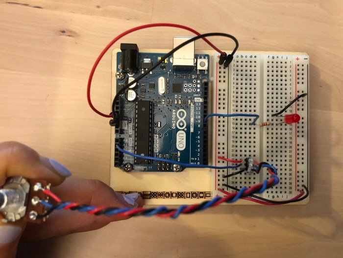
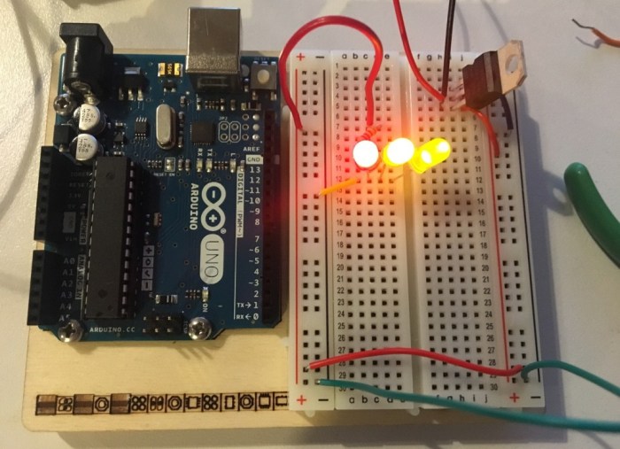
Next, I wired up the Arduino with a pushbutton, making sure that the red jumper goes to the 5V and the black goes to the Ground. On the right, is the version with 2 LEDs and the LED is in series with the 220 ohm resistor; the yellow LED is connected to Digital OutPut 4. The red LED is connected to Digital Output 3, and the pushbutton is connected with Digital Input 2.
Then I connected my USB from the laptop to my usb connector on the Arduino Uno. Last step was writing the code with an if {} else {} statement, so that when the push button is closed the Yellow is turned on, and the Red is off.
—-
Digital Input + Digital Output Lab : Project
Next I tried to do a simple application using digital or analog input and digital output. I thought that doing a stoplight would be a good project to help me understand the concepts and information that were covered in the labs and in class. So, I decided to go forth and make an LED stoplight!
First I drew a schematic of how I imagined the circuit would be (see image below). Then I tried to wire the breadboard to the Arduino. From our labs, I knew that the push button would need to be set to DigitalRead, so I did that. I also connected the 3 colors (red, yellow, and green) LEDs to their own digital pins. I used 220 ohm resistors to connect the cathode side to ground.
Then, I wrote some psuedo code to help me figure out what commands I wanted to give the arduino (see image above). I came up with:
// if the switch state is low (the button isn’t pressed), the green is on
// else if the switch state is high (button is pressed), the yellow is on, then there is a delay before it turns green
Here is the code:
And here is the final product!!
—–
Lab 3: Analog in With an Arduino
Project 5: Control an LED with a Potentiometer
Followed along with the steps and was able to have the potentiometer control the brightness value of the LED. At first it didn’t work, but it was helpful to do the “analogWrite(ledPin, brightness);” and the “Serial.println(brightness)”. When it was wrong, I opened up the serial monitor and found that the potentiometer was working correctly because the value would change as I turned it right or left. I realized it was because I was doing “analogValue = analogRead(A0)” when it was on A1.
— Analog Input Videos p.1 + p.2. Followed along with the Analog Input p.1 videos.
Project for Luv-o-Meter
This penguin’s Luv-o-Meter is done with the temperature sensor. And the more time your hand presses/ the hotter the sensor gets, the LED lights will light up more.
Apologies, this was done late in the night, and I just didn’t get a chance to properly document.
Process:
For this week’s project to work with more rule-base animation, motion and interaction, and to try making a rollover, button or slider from scratch; I teamed up with Eva! We started out by first discussing potential concepts; we both liked the idea of trying to show the phases of the moon and recreate the night sky. The elements that we decided would be changed as you dragged the slider: 1.) the different phases of the moon; 2.) the sky would gradually get lighter, 3.) the brightness of the stars and # of stars would increase.
Below is a storyboard of the sketch that describes all the parameters, sliders, and visuals we were trying to achieve after our initial meeting.
Initially, Eva and I thought the moon phases would not be too difficult to recreate. Eva had mentioned trying to solve this by overlapping a shape that would mask parts of the moon circle. But as I was sketching the storyboard on illustrator, we realized it would not be that easy. These were not perfect arcs that we could work with. We tried to think of different solutions (i.e. bezier curve, this html jquery plugin, etc). Thankfully we discussed with our professor and she pointed out an image load function that would allow us to make something like an animation for the slider.
Since Eva is more experienced with coding than I am, she was up for the challenge! It’s so great, because with this project I was thinking I’d have to change the concept to match my skill level (like with the last project). But Eva was ready to tackle the task of coding the animation + slider element.
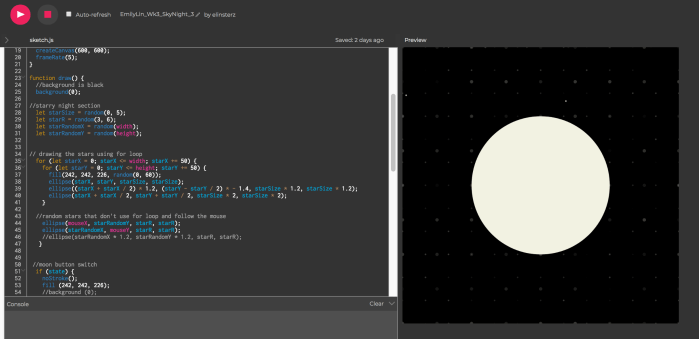
So as she worked on doing the complicated moon phase, I worked on trying to create stars in the background using an algorithmic design with simple parameters, and not just use random (). I ended up using the for loop () function. I was however having trouble with making it look random with the for loop(), therefore I played around with different sizes and opacity levels to create the look of randomness.
I wanted to make sure I learned about how the interface elements worked, so I made a separate version (before Eva and I met up to combine our codes to one) that tries out a different concept than our storyboard. My practice interface element version has a moon/sun act as a button switch. The sun is a button and when you click on only the sun, it’ll change to be the moon and the background colors will change to go with it. I was trying to create a slider that also adjusts the intensity and # of the stars, but I was not getting it. I am going to ask during the help session and just spend some more time on doing this star slider/knob.
I wasn’t happy with this one’s star pattern. I didn’t like using opacity for this design, but that worked the best for using a for loop for the stars.
For my personal sketch before meeting up with Eva, I just decided to embrace the grid like structure of the stars and just have it as a design element. I think I’m happier with this below version (for the stars) than the above. https://editor.p5js.org/elinsterz/sketches/Sk0PS-VFQ
It was great when we met up to share our progress on Saturday! Eva shared all the code that she had written for the moon slider. She also shared all the troubleshooting she had to do to get it to work, which I really appreciate! It is amazing to be partnered with someone who is both willing to explain and is good at it! So I think I understand the concept of how the images were loaded, though I have yet to try it myself and practice. I also think I understand the basic idea of why she had to hard code the images in (because of a p5.js bug), instead of being able to use a loop to call the different images each time. I shared my versions and my for loops code for the stars; however, we decided that the stars still looked like they were on the grid too much. Therefore, we just wrote a new version that uses the random function. I then hard coded in some static stars in the background so it didn’t look to empty.
I am especially grateful for Eva and how she has been patient and kind enough to walk me through her steps. I’ve learned a lot just hearing about how she troubleshoots an issue and her process for coding. It’s been wonderful working with her and I hope we can continue working together in the future.
Though the final result at the end of this week was not exactly what we had mocked up, I’m hoping that we will continue to build out all the functions we had imagined. If not in this course then at least during winter break. We think this could be a really fun series to work on and to help us (or at least me) practice! Overall, I really enjoyed this project and getting to touch upon interface and more interactive elements!
To be honest, this week I spent much more time trying to figure out the solutions for the quiz that I didn’t work on the assignment as much as I wish I had. I do think that solving the questions did help me understand the knobs and sliders more. But I will want to do more exercises and personal sketches that utilize the complicated knobs and sliders.
The quiz questions were extremely challenging for me, but they were so great for testing my knowledge and getting me to better understand if statements, for loops, and booleans (which I specifically still need to practice a lot more of). Throughout the process of trying to answer the questions, I’d watch the Code Train videos over and over. When I would think I understood it, I would try to solve a question and realize that I actually didn’t quite understand how it works. I also notice that we are starting to get into the parts of coding that require more problem solving. This is all exciting, fun, and fulfilling when I actually write a code that solves the prompt; however, I can tell that I’m working out a brain muscle that’s not used to being used. It’s amazing that I get this opportunity to practice and push myself with code every day. I just have to accept that it won’t always be easy and that certain coding challenges will take me longer than I expected. I’m eager to keep practicing so that I can be faster , smarter, and better at this.
For this project to make our own switches, I initially thought about using the RGB LED (the one with 3 legs and one leg for ground). I remember seeing/ using this LED in the Arduino Uno kit, and I was tempted to use it again for this.
At first I wired it with a tilt switch, but the effect wasn’t that cool or dramatic. The LED would ever so slightly change from one color to a lighter version of that color when it was titled. Above is an image of the schematic and the LED.
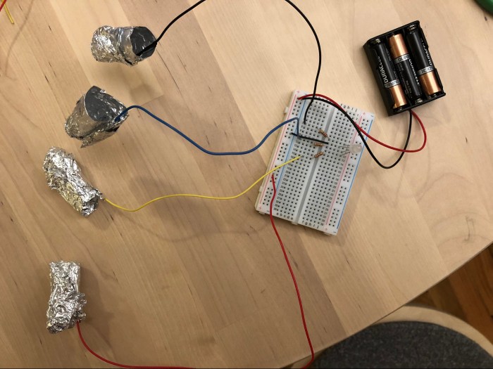
I wanted to make it more clear that there were 3 different colors that this LED could emit. Since I’ve been painting my nails more often lately, I thought about utilizing my fingernails to close the circuit. This way I could have each finger correlate with one color. And there would be a fourth wire (the red one in this case) that would be the positive terminal of the battery. When the foil finger of the red wire connects with one of the 3 fingers it closes the circuits and emits 1 specific color of the LED. So one leg is R, another G, and another B. When all the foil fingers touch, they combine to make white.
I first wrapped one of the wires connected in foil to try it out. When it worked I went on to wrap my other three fingers in foil. The image below shows the setup of the circuit with the foil fingers.
And this video below shows the full interactive function of the switch!
What a fun project to work on! I’m glad I decided to do something other than the tilt sensor. This is much more exciting and I can’t believe I’m using my fingers to mix colored lights! Crazy!
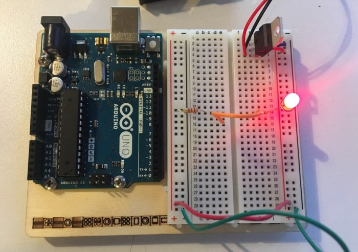
I followed along the three examples to find out if the LED would light up. I tried to guess first, but before checking the answer I tried to set the circuit it up myself. Below are 3 examples.
Answer 1:
Answer 2 (the one that doesn’t light up):
Answer 3 (the one with the LEDs in parallel):
As a test for myself, I tried to set a circuit up with the LEDs in series, instead of in parallel. Below is the result:
This was a very helpful lab for familiarizing myself with the concepts we have been reading about. It was a great hands on experience in setting up the breadboard and trying to get the jumpers to connect properly.
After finishing, I read the note about trying to have the colors be as consistent as possible. I think that I did not do a great job at color consistency in this lab, but moving forward I will definitely need to be more organized about making sure that the green/black = ground; red = power; white/blue = data.
Lab: Electronics – Using the Multimeter
Measuring Voltage
1.) As shown in the reading, I used the 5V output from an Arduino and added an LED and a 220-ohm resistor to the breadboard. Next, I measured the voltage between the power and ground bus rows on the breadboard. It took me a while to get the multimeter to not jump around and stay on a number, but eventually it showed a consistent range between 4.5 – 4.8V. (Video below)
2.) Next I measured the voltage drop across the LED by putting the leads in parallel with the LED. The reason that the voltage drop is the same when I put it in parallel is because the voltage in parallel is not split (like it would for amperage). Below is a short video of this process.
Switched LED Circuit
1.) Wired up the circuit to include the switch before the resistor and LED. It is great to keep in mind that LEDs usually consume 2.0-2.6 volts (V) and 20 miliamps (mA).
I measured the voltage of the resistor = 2.8 volts voltage of the LED = 2.03 volts total voltage between power and ground = 4.82 volts The voltage of the LED + Resistor is around the same amount as the voltage of the total circuit.
Adding up Voltage
Next, I measured the voltage across a circuit that has 2 LEDs in circuit. The result was almost accurate, but I was off by 0.37 volts. Here are the measurements:
– LED1 : 1.73 volts
– LED2 : 1.93 volts
– Resistor: 1.07 volts
– Total voltage between power and ground (when measured): 5 volts
– Total voltage between power and ground (when calculated): 4.73 volts
Components in Parallel Measuring Current
I measured the current through 3 LEDs that were in parallel. The circuit was completed when I put one lead in the ground and the other in parallel with the LED’s cathode. The measurement of the current was: 4.47 mA
Generating a Variable Voltage with a Potentiometer
I measured the voltage between the center position and ground with the potentiometer added to the circuit. I noticed that the multimeter number changes as I turned the knob.
—-
Questions:
1.) I tried measuring the resistance of a diode, but the number started high from 10MΩ and continued to decrease; however, the number did not “flash briefly on the meter, then disappear” as described. Is that okay? When is it important or needed to check the forward bias of the diode?
2.) I put the LED in reverse to try and measure the negative voltage, but the multimeter didn’t show any negative number for the voltage. Why?
3.) Why is there a “Warning: Measuring amperage with the red probe in the voltage hole when you have no idea how big the current is, or measuring voltage with it in the amperage holes is a good way to damage the meter.”? I think I need more clarification about how to measure the amperage through the LEDs in the circuit.
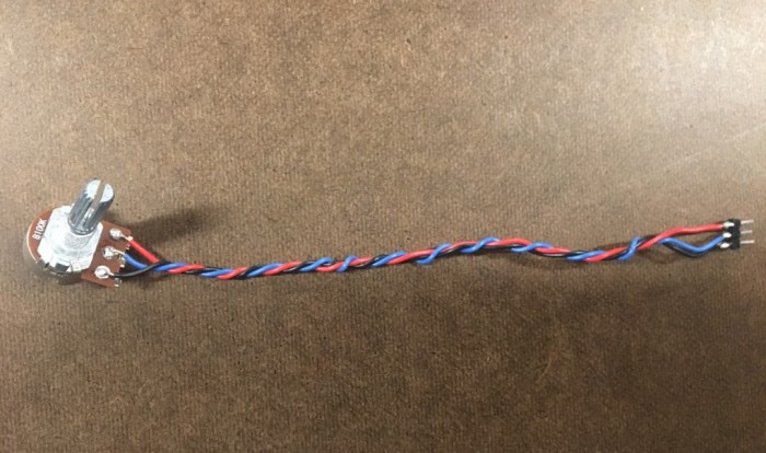
– First, I got all the materials listed in the ready. I used a potentiometer I found in the shop.
– I used the wire cutters to strip a 1/4″ of insulation off the wire. Then I threaded the wire into the holes of the potentiometer. I ended up cutting of the legs of the potentiometer, since I wouldn’t need them anymore and they were getting in the way when I tried to thread the wires.
– Then I melted the soldered the aluminum to the wires to have it connect with the potentiometer.
– Using the multimeter, I tested the resistance between the red (voltage) and black (ground) to make sure that I didn’t short circuit any of the 3 wires.
– After making sure nothing was short circuited, I used the hot glue gun to insulate the wires.
– I am hoping to use this soldered potentiometer in the circuit lab that I will do next!
Reflections:
Soldering is incredibly fun and very meditative; it reminds me of threading a needle and embroidering. I especially love it because of the detailed nature of the work. There’s a calmness to the work that I appreciate.
Questions:
1.) “How to Solder Video” (5:14) – why can’t the longer and shorter part touch of the DC power connector? What will happen?
2.) What is the point of tinning? Why does it need a thin layer of tin?