Sukanya, Sid and I worked came up with many ideas. Below are some of the sketches – it was not easy for us to decide. After many different ideas and exploration, we decided to make a kinetic hammer. We were inspired by Professor David Rios’ kinetic pedal synth. See here for reference video: https://vimeo.com/66357163
So we booked office hours with him to go over the materials and advice. We then sketched out a general idea of the circuit and form.
As we were making it, we realized how similar this tube and spool device was to the comedic “ShakeWeight” workout device. So we switched our idea to be a kinetic shake weight! See infomercial below!
For fun, I tested the magnet wire! Pretty cool.
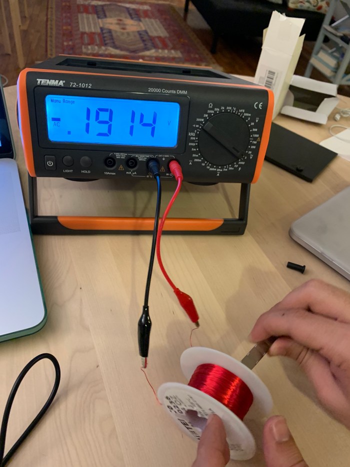
Then, I tested the amount of voltage it generated without the diode rectifier to convert the current to DC.
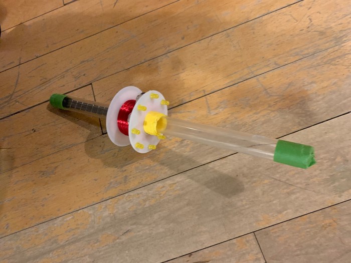
We put all the parts together to make just one part of the hammer.
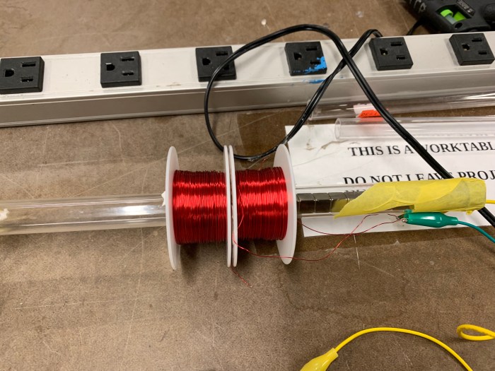
We ordered the parts very last minute, so we only had these 2 spools and those magnets to use. The rest of the parts we bought from canal plastics and canal rubber.
We first made the circuit with the diode rectifier and hooked it up with the multimeter to read the amount of voltage generated when we shake it. See Sukanya below, shaking to generate voltage.
We then added the LEDS to the breadboard to see how many we could light up.
We could light up many it turns out! We put them in parallel with 2 pairs in series.
We drilled holes on the top of the wire spool for the LEDs. Instead of 4 diodes as the rectifier, we used a rectifier chip and attached it to the bottom of the spool. Then voila, here’s out LED Shake Weight!
——
As we waited for our materials to be shipped, Sid made another project with a stepper motor!
This is not that early morning and almost noon time as the shadows indicates. The shadows are slanted at around 4pm/ 5pm on a clock, which makes a lot of sense since this was taken near 11am morning. They are also crisp and create dark, cool shapes. Even the ridge running along the middle of the rooftop is almost a pure black. The side of the building that I am taking a photo faces east.
—
Night Scene:
02/12/19, Tuesday, 7:45pm
Broadway & Lafayette, New York
Although it is night time, it almost feels like it isn’t. This is partially due to the spotty and colorful light situation. There are multiple sources spotlighting specific regions. The headlights from the vehicle shine their bright lights on the roads, highlighting the grooves the cars have created on the slushy surface. Other vehicles in the background are also casting a sharp fluorescent light onto the ground. The three dimensional form that the snow and water have created are especially fun to look at because of the harsh and spotty lighting situation. Because of the bus lights, the raindrops are more clear and obvious to the eye. Even when the snow is a mushy mess, I still love seeing how light glistens and reflects off of it.
Interaction: When you touch the circle “button”, the light will go to flickering state. If the button is pressed for 2 seconds, the light goes to “wild” flickering state. If the button is pressed for another 2 seconds, the light will go off. After 5 seconds of being off, the candle will light up again.
——-
This week, I was excited to a.) capture the beauty and movements of a candle, b.) switch my work flow so that I program more. My personal goal was to try and spend less time on fabricating and challenge myself with the code.
a.) I first tried to map out how the LEDs of the Neopixels are numbered. This helped for making arrays and knowing how the indexing would work.
b.) I observed the candle and ideated the various states that I wanted to recreate.
c.) Based on the flickering/ blowing out candle observation, I decided on 2 states, but initially ended up with 4 states: a.) calm, b.) crazy, c.) wild, d.) off.
Calm = normal state
Crazy = flickering
Wild = randomly wild flickering (like right before a candle blows out)
Off = when it’s so wild that it eventually blows out.
d.) Simple fade: I first attempted to do a simple, pulsing fade that loops through all the neopixels. Here is my code for that.
e.) Different intensities: I tried to create my initial 2 states (calm and crazy). I used a touch sensor to switch between the states, but was not set on using it as my final sensor. I was still hoping to play around with different sensors.
d.) testing piezo (ultimately unstable, therefore fail): I tried testing the piezo, but when I console logged it, the reading of the amount of movement was very unstable and hard to get the lights to show the different states.
e.) testing accelerometer: I really wanted to try the accelerometer for the candle. I was hoping that the more you move the candle, the more it would flicker and eventually go out like a flame. Unfortunately, I ran into road blocks with my code and my soldering for the accelerometer went loose. I also realized from this test that the interaction would be weird if I had the wires attached to the arduino like that.
In the end I decided against using it for the final piece, but did enjoy trying to learn how to use an I2C accelerometer. Here is my code for that.
f.) Timer: I just had to bring this up because it caused a headache for me. At first I used the Simple Timer Library. This was helpful but realized it counted the seconds from the start of the program. In order for me to have my touch sensor react to the amount of seconds that is being pressed, I needed to record that press time into a new variable. I ended up not using the Simple Timer Library, but writing my own if statement to create a timer that starts when the button is pressed.
g.) Form: Unlike my usual flow, I focused on the form after I had figured out my code. This was very hard for me to do since I normally want to jump into making the physical product. Nonetheless, it was good practice for me to push myself. By Monday, I was able to start making the the enclosure and diffuser.
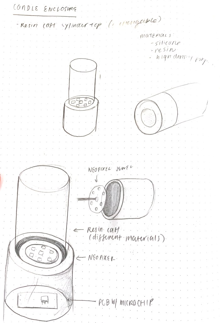
I thought of different types of diffusers: resins, paper cylinders, already found containers (gum bottle). See sketch below.
In the end, I decided upon a crystal. I found the refracted light in the crystal rock to be so magical. It really distorted the light so it was hard to tell the source. It also reminded me of the rocks used in fireplaces. See below for example.
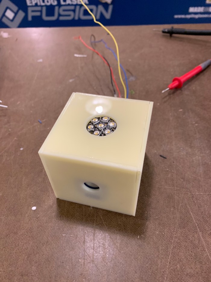
I decided to go with it and focus on how to enclose the touch sensor and Neopixel in a way that would go well with the rock. I went simple and used white acrylic I already had to build a box to house the touch sensor.
I also wanted to make some holders for the touch sensor and the neopixel to sit on nicely. See sketches below for my mounting ideas. I combined with my subtraction homework to use The Other Mill, to get a 2.5D part.
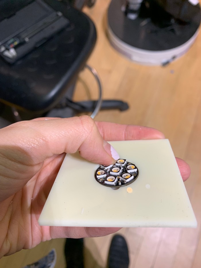
Soldered my Neopixels and sensor on a pcb board.
Enclosure close to being done!
After doing this I realized, I am not a big fan of the white acrylic. It made the enclosure look slightly translucent, but it was too late in the game to change. Ideally, it would be black acrylic, not white.
I added the crystal on the top and added in one extra in between calm and wild state, called crazy state.
Very exciting to use the The Other Mill! Again, I combined this with my light & interactivity class, and cut sensor and led holders for my candle enclosure.
1.) Made measurements of my parts and enclosure on paper:
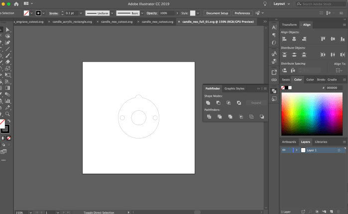
2.) I went on Illustrator to create all the svg files for the cut outs and engravings.
3.) Placed the files in Bantam Tools and adjusted the settings to fit my 1/8″ flat end bit and my 0.125″ sheet of acrylic.
4.) After inserting my bit into the machine, cleaning the acrylic with the alcohol cleaner, and double stick taping the back. I went on Batam Tool GUI. First thing I did was home the bit. Next, I began milling! Woohoo!
5.) Pieces are cut! Engraving is also there! This is all too exciting!
6.) Piece 1: Holder for the Neopixel
7.) Piece 2: Touch Sensor holder. Engraved the part with the solder and metal sticking out from the other side.
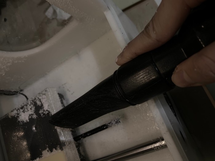
8.) And most importantly, I cleaned up! It gets pretty messy in there, so I made sure to clean up my winter snowstorm.
Our kinetic energy group (Sukanya, Sid and I) tried out a few steps using the stepper motor.
a.) We used the stepper motor, this is AC so we needed to add the diode rectifier to convert it to DC. We added a 470 µF capacitor, after the diode rectifier and before the LED in the circuit.
b.) We then took out the LED from the circuit and added the Watts Up device to our circuit. The Watts Up device is reading the volts and watts from our capacitor.
c.) We added the LED back into the circuit with the Watts Up device.
d.) Then, we added the switch to the circuit so that we could store up the volts in the capacitor until we discharged by toggling the switch. With the stepper motor and string we were able to easily get up to ~4V (unlike with my hobbyist DC motor) before discharging.
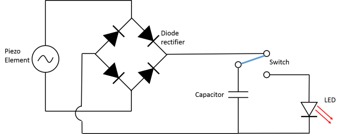
Before realizing that we needed to power the led with either a magnet and coil or a dc motor, I looked into a couple of other different ways to power the led with kinetic energy. One of the more intriguing ideas I stumbled upon was the piezoelectric. I found this schematic online that I found extremely helpful even when I changed over to using a dc motor instead. This schematic (found from teachengineering.org) had all the components I was looking for: diode for back voltage, capacitor for storage, switch and the led.
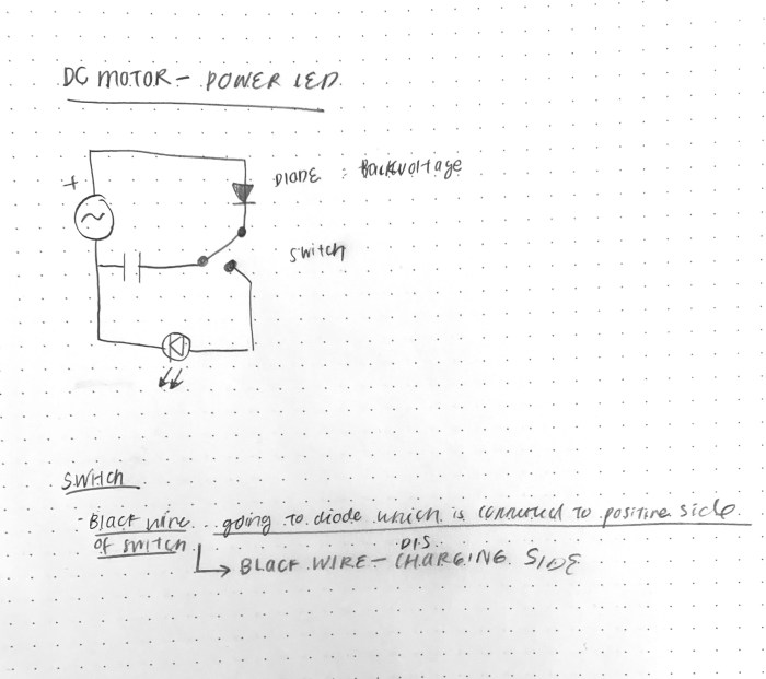
To make this work for the dc motor, I changed the diode rectifier in the circuit to a single diode. Below is the adjusted schematic.
The kinetic energy is converted into electric energy by the dc motor. This energy is stored in the capacitor. The diode is added to the circuit to prevent the capacitor discharging into the motor. When the switch is turned on the energy in the capacitor is released into the LED. The amount of voltage needed to power this LED is ~2.5 – 3.
Below is the circuit that uses the multimeter to find the amount of voltage stored in the capacitor as I spin the motor.
One of the main troubleshooting issues was not knowing how much voltage to charge it up. It also took a while to figure out this circuit.
Below is the video that shows me hand spinning the motor till it reached 2.58V. After it reached 2.58V I turned the switch to charge the LED.
a.) I tried to combine this fading led project with my subtraction assignment, which was to make this awkward circle with a cut through it. As I was looking at the diagram for the piece we needed to make, I realized it looked a lot like a toaster! So, I decided to make the fading leds look a bit like the fire in a toaster. Sketch below.
b.) Below is the schematic for the 5 fading leds and the steps I would need to take for it.
c.) I did my circuit first with just one fading led.
d.) Then I added the 5 leds, alternating reds and yellows to hopefully achieve a more fire-y glow. I also added the sin function to the code.
e.) Circuit looks like the photo below.
f.) After getting the circuit and code figured out I moved onto the enclosure and soldering the leds to a thin pcb that would fit in the toaster lamp.
g.) I then had the wirees for the leds and the potentiometer come out of a hole I drilled in the back of the lamp. I also attached a little cap I had to the pot.
h.) Below is the view of fading leds from top view and with a junk acrylic.
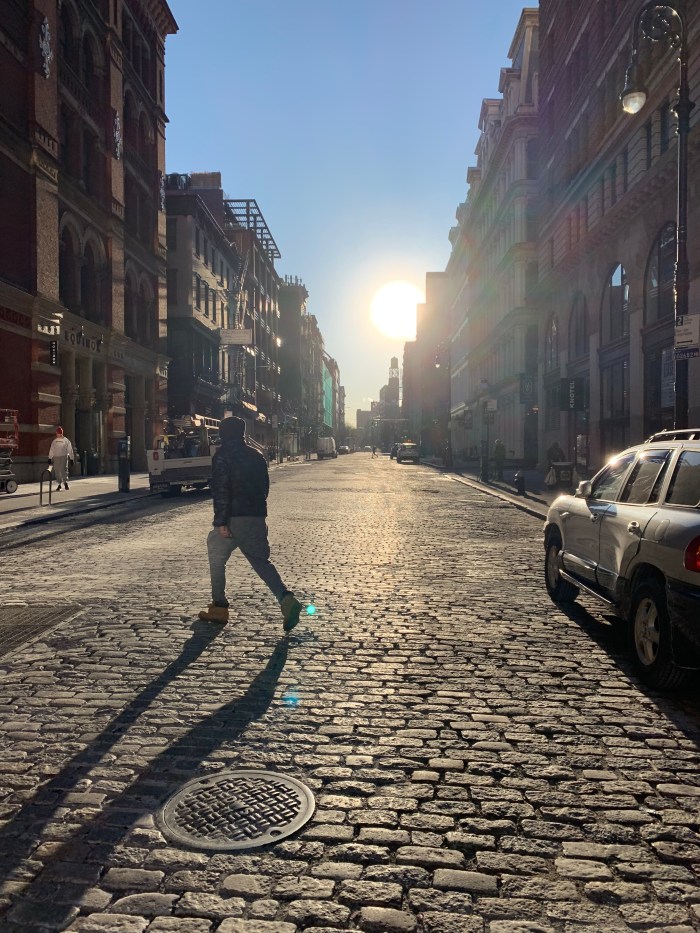
Thursday, 1/31/19, 8:21 AM
Broadway & 2nd St., New York City
A white orb of a sun rises from the east. It is amazing how the sun looks when captured on camera. The sun itself is the whitest spot in this photo. If I used the eyedropper to determine the color of the sun, I’m sure the hex would be #FFFFFF (heads up, I tried it and I was right it is indeed pure white!) Equally beautiful is the peachy glow that emanates from the sun and softly transitions into the sky blue. My favorite part is when the color of the sky mixes with the peach of the sun to make that complex green shade near the horizon.
The sun, when it is at this low angle in the morning, casts cool, long, lean shadows from the east to west. With this much bright light, the cellulite-like tops of the cobblestone are accentuated. The pattern of the road become all the more distinct, making the crevices of the road seem deep.
At 8 AM, everything that is exposed to the sun light is extremely bright as shown from the extreme highlights bouncing off the mid-street person and the van on the right. The man and the light post are outlined by a thin strip of highlight. Everything else that is not directly facing the sun, is backlit and hidden in shadow. What a lovely moment and time of day.
—
Indoor: Candle
Sunday, 2/03/19, 7:30 PM
Midwood, Brooklyn
In this case, I don’t think the video does the candle light justice. The subtle nuance of the color within the flame are not accurately shown via camera. I would describe the flame as having 3 color parts: blue at the bottom, transparent in the middle, and a opaque yellow for the tip.
A rich sapphire blue is outlining the bottom cusp of the flame, where the candle wick and the melted wax meet. Surrounding the wick is a slightly transparent pale yellow in the shape of a stretched out ellipse. This transparent part changes to a more opaque yellow at the top, which forms the tip. The tip is mesmerizing because it looks like strands of hair sometimes; it is not always a perfectly round point for the top. Instead it feathers and blurs out into the air.
The more I move, the more the flame moves unpredictably. When the flame is flickering sporadically, it is so fast that I feel as though my human eye can’t perceive its motions properly. Even when the flame is at its stillest, it is still gently moving and circling in gentle swaying motions.
I also used this opportunity to make an enclosure for my fading led for my Light & Interactivity class.
a.) First, I printed out the instructions so it would be easy to follow along. Next I made measurements on the large wood piece that I found marked “free”. A lot of great free wood lying around this time of year! I wanted to do 3 for extra practice, and to use the positive shape of the design for my lamp.
make measurements on wood
instructions
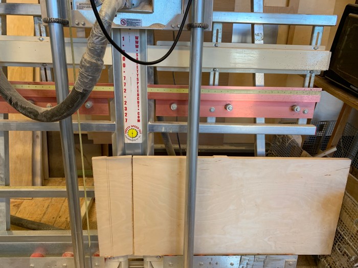
b.) Next, I used the large wood slicer machine (forgot the name) to cut up the wood into smaller panels. I used the miter saw to get the pieces to be exactly 1×1′. I soon realized this was unnecessary to cut the panels to be exactly the same size of the diagram at this stage, because I would have to drill screws to secure the piece.
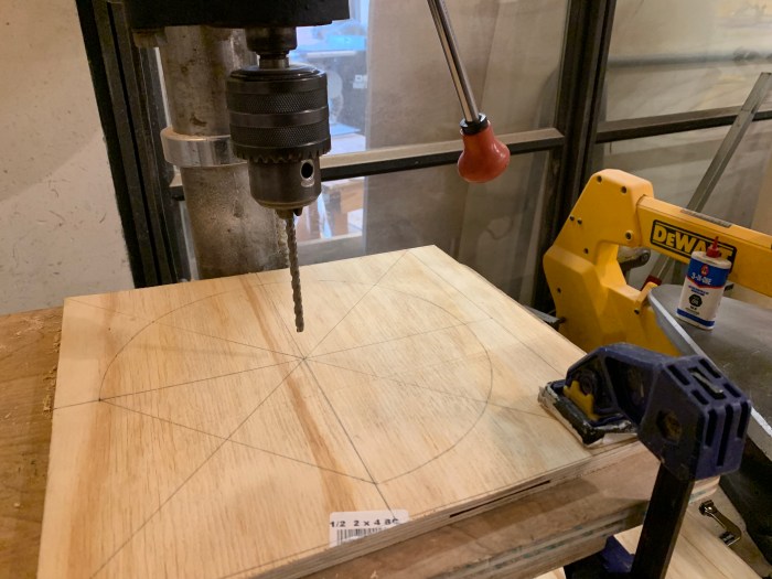
c.) I drilled the hole for the wooden peg using the drill press. I didn’t read the instructions carefully enough, so I accidentally drilled completely through the wooden panel. This did make it hard for the peg to stay, it would’ve been better to drill partial way through (as suggested).
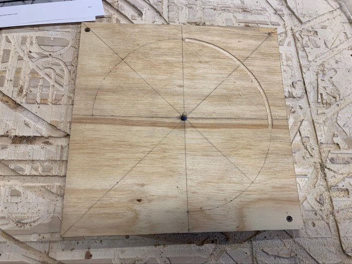
d.) I drilled screws on opposite ends of the wood to secure it to the CNC. I used tape to make the wooden peg a little thicker and to stay better in the piece.
e.) I unscrewed the top part of the router and tapped out the saw dust that was stuck. Then I screwed it back on and inserted my bit in using a wrench.
f.) Great, now the bit is nice and screwed on. I then adjusted the router’s height to try and get 1/8″ of the bit above the the top of the circle jig.
g.) I made my first very shallow cut.
h.) Then, I kept going until I reached the bottom of the wood. I accidentally placed the peg in the wrong part of the circle jig and made a cut outside of the intended line.
i.) Using a caliper, I measured the distance between the outside and inside of the bit to the line I was supposed to cut. Using those measurements I drew the lines for where to cut the straight line.
j.) I clamped a ruler down, changed the circle jig to the straight edge one, and began cutting along the intended line.
k.) Many times I went over the intended line. It was hard for me to see and know when to stop because much of the bit is not visible when cutting. ***I wonder if there is a better strategy to know when to stop cutting?
l.) I had 3 pieces, so I kept practicing on those sheets.
m.) I was also intending to use the positive shape of the piece to make a led enclosure. Below are some shots of the piece and a work in progress photo of the light enclosure.
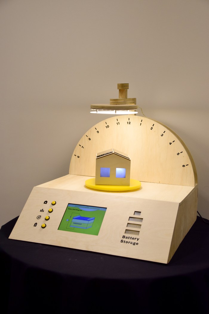
My aim with this project was to create an educational tool that explains how solar panels work and how sunlight is converted into electricity.
The objectives for “Power Your Day with Sunlight” is to visualize the science of solar cells and to better understand this modern technology. By providing the user with a hands on model, people will be able to experiment with how solar cells correspond with the sun.
—
b.) Why I made this:
With the threat of global warming, it is obvious to consider alternative energies such as solar. Since the sun is both free and gives off more energy than we would ever need to power everything we use, it makes sense that we are seeing a slow rise in the use solar panels.
At this point we all know what solar panels are, but what do we really know about how solar panels work?
If it is such a great alternative, why aren’t more people using it? This brings up the challenge of energy storage.
—
c.) How it works:
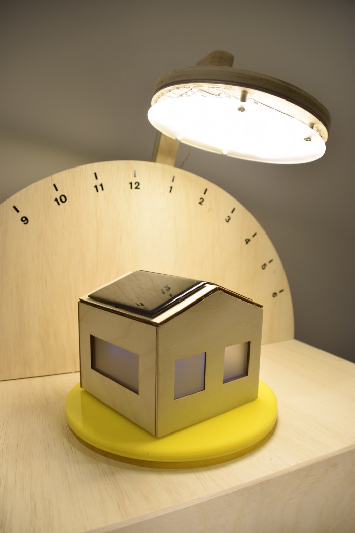
This project is composed of a physical interaction in which the angle of the light, representing the sun and time of day, is reflective of the light generated inside the miniature solar house. Meanwhile, the screen below the house displays an interactive animation of a solar cell diagram that updates in real time based on the amount of light that the solar panels receive. Next to the screen are four buttons that will change to different web pages. The first button will display an intro page, the second page will allow show the voltage generated by the light in the form of a moving bar graph, the third one displays the solar cell schematic, the fourth button displays information regarding battery storage.
On the right side, there is an LED powered button icon. When the light is shining on the solar panel, the battery icon will cyclically flash to show that it is storing the solar energy. When the light is turned off, which will automatically happen after the day has ended, the battery will discharge. At that time, the screen will show a page that discusses the current status and challenges with the development of cost-effective batteries.
—
d.) Live demo:
Power Your Day with Sunlight – Quarter, Full Interaction from Emily L on Vimeo.
* Sorry, not using github properly in this instance, will work to better understand github so as to not create a messy repo.
f.) Credits:
This project was completed with the helpful guidance of many supportive experts. My most sincere gratitude goes to Professor Tom Igoe, Luisa Pereira, Kasra Sardashti. I’m especially thankful to have such insightful technical and conceptual feedback from my pcomp professor Tom, icm professor Luisa, and life partner/bff/ troubleshooter extraordinaire: Kasra. These people and this place (itp) make it possible to do these fun dream projects. I’ve learned so much from trying to understand, mold, and execute this solar interactive because I had the access to these people.
Also, thank you to my itp classmates/ friends who provided insightful feedback throughout this process.
Thank goodness for the amazing residents Jasmine, Koji, Yeseul, and Alejandro. What a good support system during pressured times.