This week I tried to play around with the DMX lights on the ITP floor. I used the Elation Platinum Spot Pro II. Here are the steps I went through to control the DMX lights.
a.) Getting the right cables was half the battle. It was important to get the ENTEC cable, the XLR cable and a 5pin to 3 pin cable.
b.) Next was controlling the DMX Lights with the QLC+ Controller.
Things I realized along the way and was reminded of:
The data sheet for this is so helpful
The channel begins at 101 in the QLC
I also wrote down my own channel “datasheet” using language that made sense to me.
Enter a caption
d.) Helpful command lines when trying to use command line to run node file:
ls /dev/tty.* (lists available serial ports)
ls /dev/cu.* (lists available serial ports)
node “file name” (runs js file)
e.) I tried to use the command line to run the file “simpleTest.js”
Unfortunately, I was not able to actually run this file because my serial port was not showing up. It may have been the cable, but after switching a new cable the file still would not run. I am left unsure of how to get my serial port to show up. I will update you on the progress on this end.
Worked like a charm! Now the usb port shows up when I run “ls /dev/tty.* (lists available serial ports)” in the terminal! Thank you Tom for the help with this!
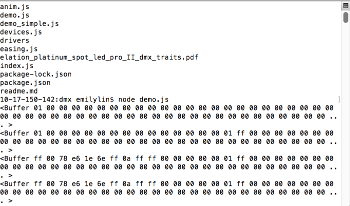
g.) Running “node file name.js”
I ran the demo.js file from Tom’s repo, in my terminal but it started buffering. I’m unsure why.
Solar energy will power the wireless communication device and temperature/humidity sensor. When an unhealthy (for the bunny) combination of high temperature and high humidity is measured, the feather RF will communicate to the other feather RF to use the relay to turn on the fan. The fan will then be used to cool the bunny (yay!).
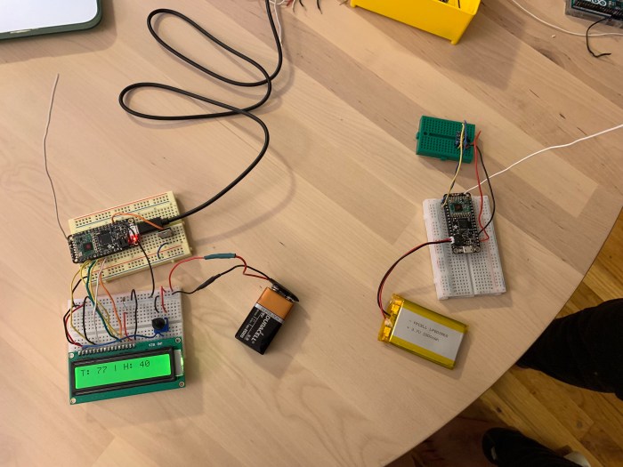
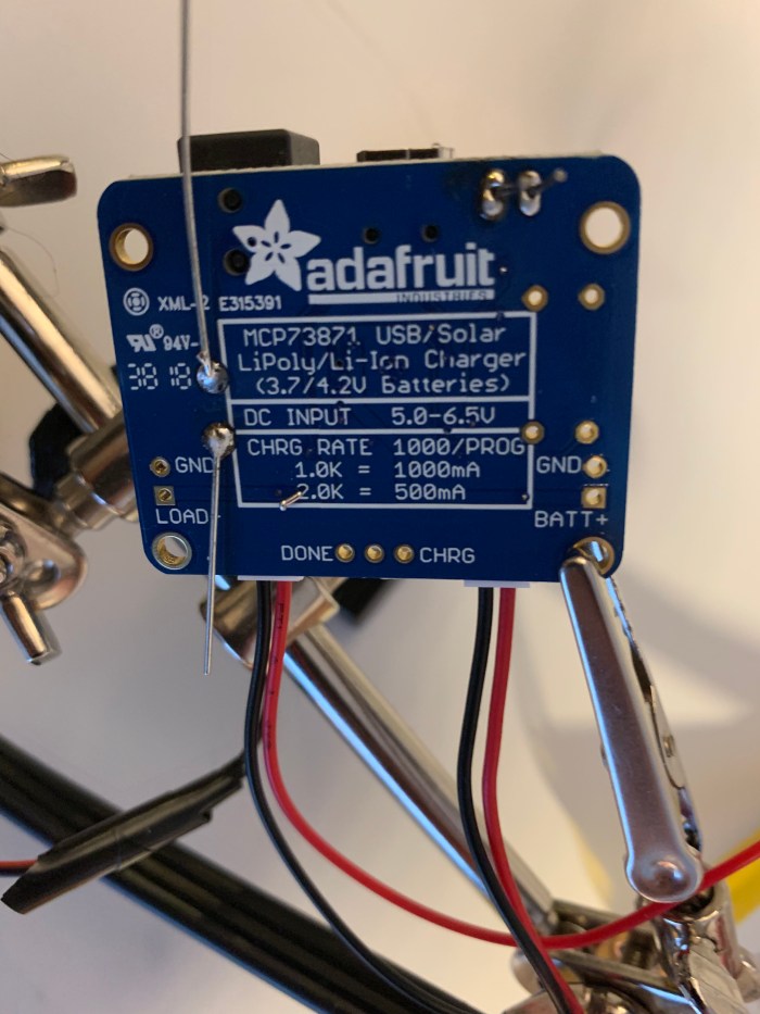
Bunny Bot TX (left) transmits the signal using Adafruit’s FeatherRF. On Bunny Bot TX there is a solar panel mounted on the back. The solar panel is charging a 3.7V, 2000 mAH li-poly battery that powers the temperature sensor mounted in the nose of the Bot and the Feather RF. When the temperature is over 65 F, the Bot will transmit the temperature to Bunny Bot RX. If it is not over 65F, the Bot will send a message that says “Cold enough for pashmy!”.
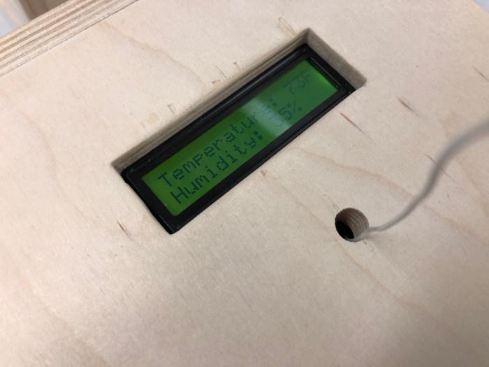
Bunny Bot RX (right) receives the signal also using the Feather RF. It then displays the temperature and humidity on the LCD display. When the temperature is over 75F, the fan located in the mouth of Bot RX will turn on. The fan is connected to a transistor which acts a switch to turn it on or off. The LCD display and the fan are powered by the 12V DC adapter. The Feather RF is powered by a 3.7V, 2000 mAH li-poly battery.
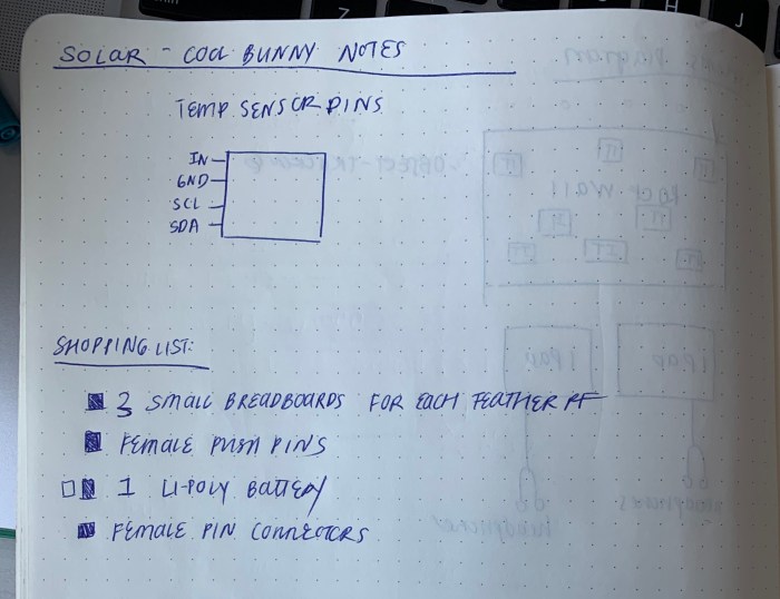
a.) Combine circuit of Feather (TX) with Temperature Board A (this is the board that will transmit data and read temperature + humidity. solar panel hooked up to this feather)
—
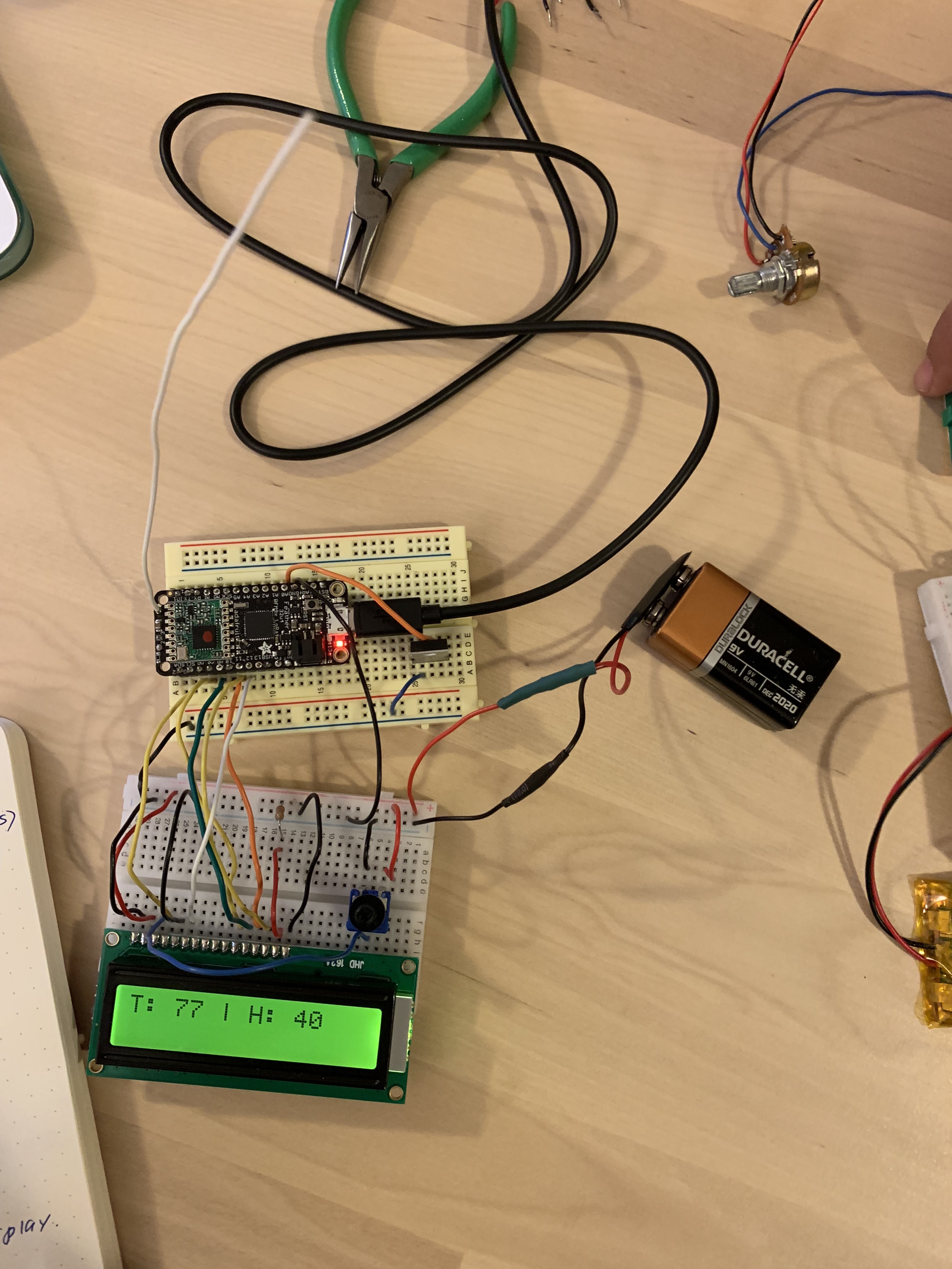
b.) Combine circuit of Feather (RX) with Temperature Board B (this is the board that receives data and displays the data on LCD. If temperature high enough it will turn on the fan)
Here is the Feather TX and Feather RX boards together (both with their adorable little antennas!)
—
c.) Turn on fan with new Temperature Board B
—
d.) Put fan and LCD board on 12V adapter
Notes on measuring the right resistor to put when using the 12V adapter to power the fan and the power the LCD display.
—- e.) Attach solar panel to Feather TX board
—
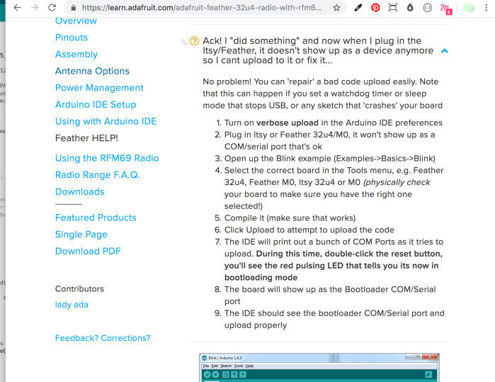
f.) Deep Sleep Libraries
For resetting the Feather when port stops showing up:
However, for the class demo I will not be using the version with the SleepyDog library, because every time I run it, my usb port gets disconnected and I can’t communicate with my feather RF anymore.
Once the bunny bots are back in my apartment, I will uncomment the SleepyDog code out and run it and just let the feathers do their thing.
—
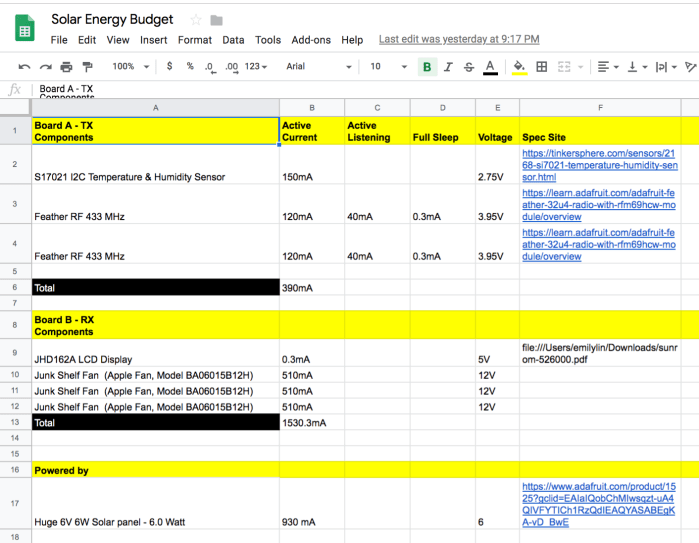
g.) Edited energy budget:
h.) Fabricate the bunny bots!
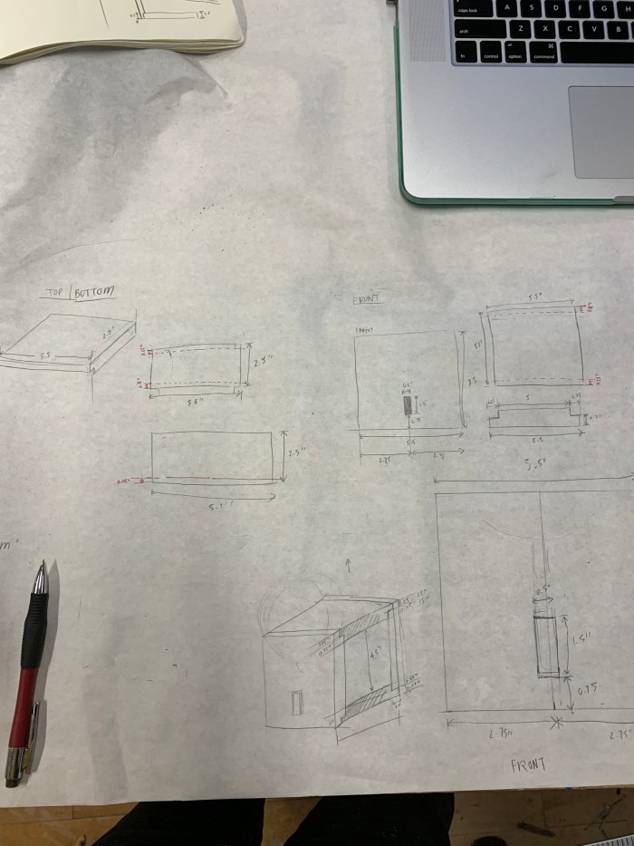
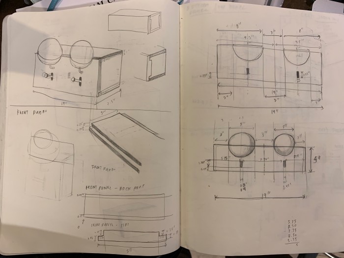
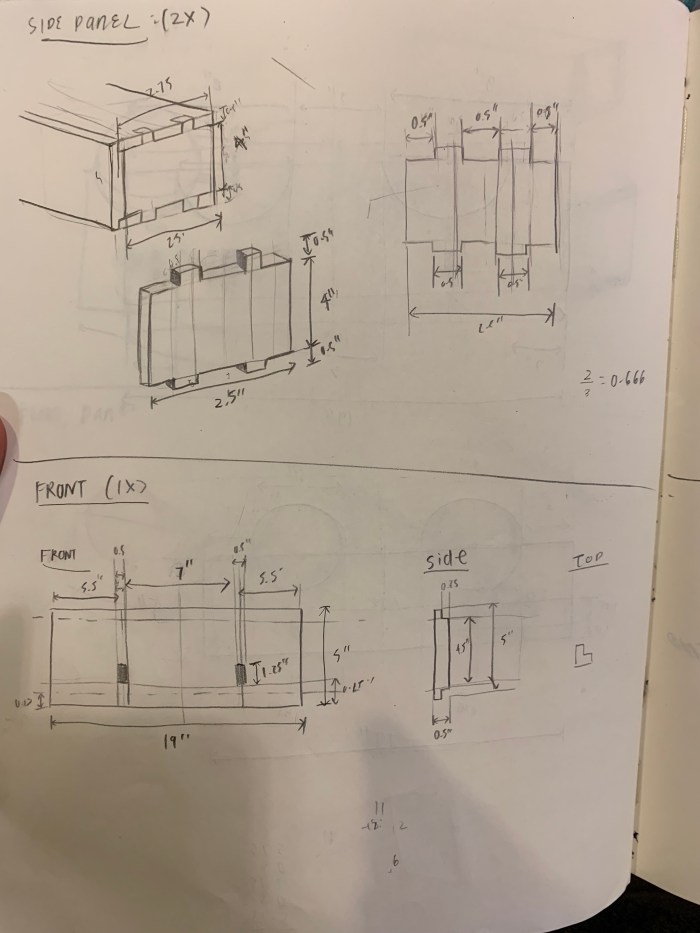
Sketches of dimensions.
This slideshow requires JavaScript.
Using the CNC to cut the bots.
2 bots done being routed! Now time to glue!
Bots are made with the components ready to be placed inside!
—
i.) Components placed in Bots
Helpful resources for understanding how to use Feather RF/ Code in Arduino:
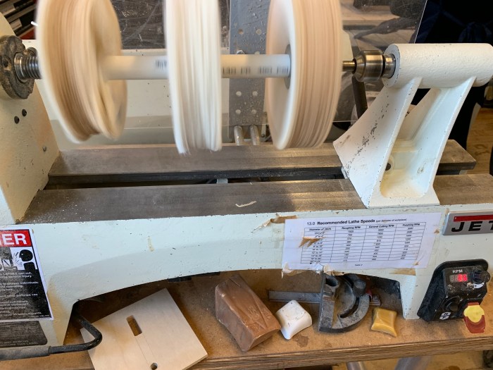
5pm is the best time to work in the wood shop. Light beams in from the upper left corner of the window because the sun is setting in the south east and the window faces east. It’s kind of a mess in there, but the way the light shines on the brick wall and the machines covered in saw dust is just gorgeous. The pictures don’t do the moment justice, because when you are in the shop at this hour you see all the particles dancing right in front of your face. It glitters.
The room is already a light tan color and at this hour the beige of the room becomes more prominent. The natural light helps reflect the beige of the space. Even the windows are coated in the beige of the saw dust. Their is a warmth in color to this space at this hour that I find relaxing.
03/03/19, Sunday @ 11:35AM Chelsea Market, Manhattan, NY
From the color, the form, the light that is cast, it is clear that there are over 3 different types of light sources from this point of view. On the right, the warm light is coming from the timeless incandescent bulbs. In the middle of the roof there are rows of LED (I’m pretty sure?) lamps hanging from the ceiling. These larger lamps are slightly cooler than the incandescent bulbs, but they might not be cool white? Perhaps just in comparison, the LED lamps look as though they are a cool white. The colors on the glossy but banged-up wood panels make this color distinction especially obvious. From the candle project, I know that the black floor boards make for an especially reflective surface.
On the left there is natural light shining through. I remember the day being sunny, but sometimes overcast. Therefore, the bright blue is definitely coming from the sky. Hiding underneath the lower roof of the shops on the right are what looks like christmas-type lights being strung.
This scene is lovely for it’s various light sources. The beams and pipes on the roof make such beautiful shadows on the roof.
1. if key is on handle: fade light on, play on melody
2. if key is not on handle: turn light off immediately, play off melody
3. if key is on handle, but room is dark: turn off light
—
Process:
This has been a bumpier week with sensors and the Arduino boards. My Arduino uno stopped working for some reason, so I switched over to the Mega. I then realized the Mega was too big for my sconce enclosure so I then switched over to the Uno.
I also changed between 3 different type of sensors (and at some point even tried copper plates/tape) before finally sticking with the force sensing resistor. I switched around so much because I realized the touch sensors wouldn’t work with my wood on wood, wood on metal mechanism – it only reacts to touch. In hindsight, it is obvious that the capacitive touch sensor (both the one with the button on the sensor and the breakout version) would not work for a non-human touch. See my (sort of) step-by-step process to figure this out.
a.) First I narrowed down my light choice to be a chip on board, instead of Phillips Hue light bulb or high watt led.
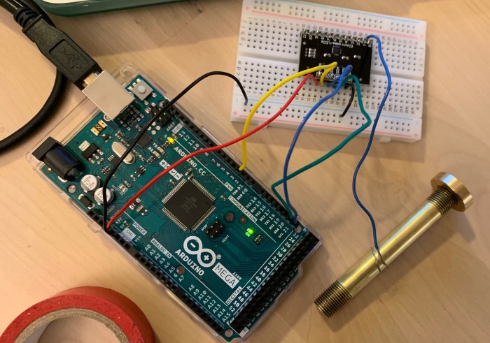
b.) I tried out my circuit with a breakout capacitive touch sensor. A whole day was spent figuring this new sensor out because I needed to review the I2C information from Intro to Pcomp. There was a learning curve with this “smarter” sensor. I didn’t end up using it because I realized it doesn’t work for keys. *The capacitive touch sensor will only register as a “touch” if a person’s is holding the key.
It works with hand touch, but not with metal touch.
c.) All the while I have been fabricating the box using the CNC. See the full fabrication process in my subtraction blog post.
Photo here of the final box, sanded and waxed.
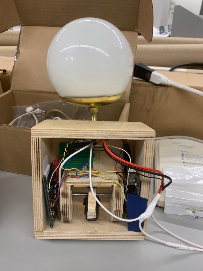
I then assembled the light fixture together. And eventually assembled all the parts. For the light fixture I ended up not using the socket I had bought because the COB was too far up in the globe. This caused only half of the fixture to be illuminated.
Switch mechanism was also assembled and full documentation can be seen in subtraction blog.
d.) After realizing that both touch sensors would work, even with the switch mechanism. I switched over to a Force Sensor Resistor. Circuit with that below.
After finalizing the circuit, I soldered it.
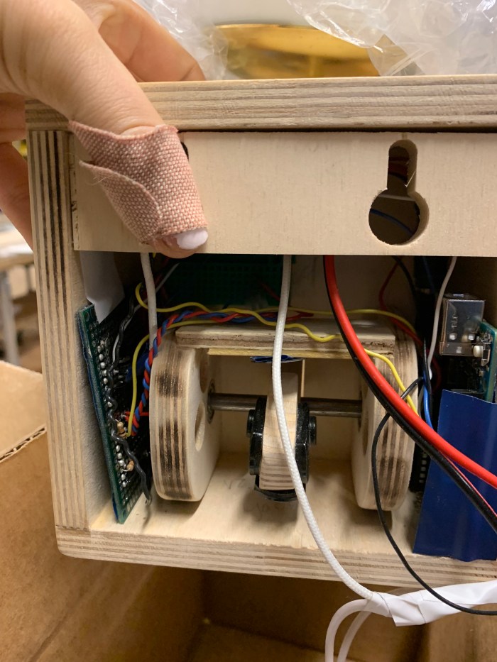
e.) I then put all the parts together: mechanical key hook switch, the pcb, the arduino. From doing this I realized how little space I had in the enclosure. The force sensor is a difficult sensor to fix properly and solder other wires to. I ended up giving it it’s own breadboard close to the switch so the little pins it has doesn’t constantly fall off.
f.) The dc adapter also had to be cut and soldered for multiple reasons. One of them being I wanted to use the white wire so that when it hangs on my white wall, it would not be too noticeable. Secondly, I didn’t want my arudino usb connected to my laptop. So, there needed to be a way to charge both the arduino and the 12V light with the adapter.
The power of the adapter was cut and connected to both the power of the dc jack plug and the power of the COB.
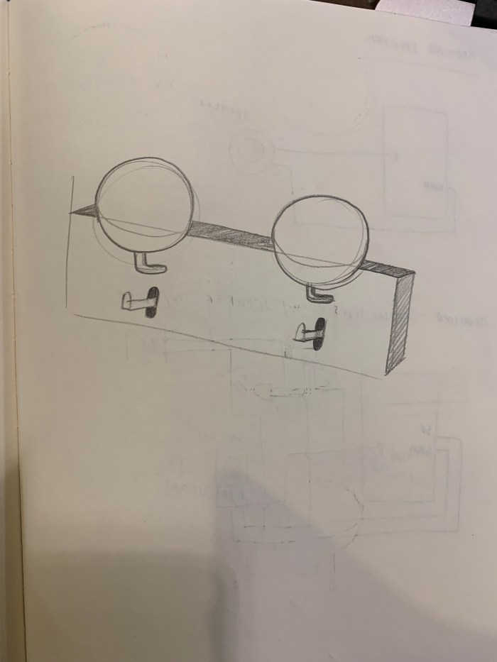
g.) Last thing was putting it all together and adding the back panel for the hooks.
—-
Helpful resources I encountered for specifically the capacitive touch sensor portion:
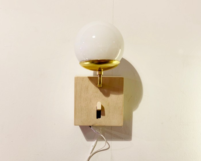
See final with all the interaction and light fixture in the light blog.
For my second attempt at joinery, I needed to redesign the dimensions so that the joints fit well. This took 3 separate attempts to get right!
1.) First attempt using new dimensions of just a rabbet joint.
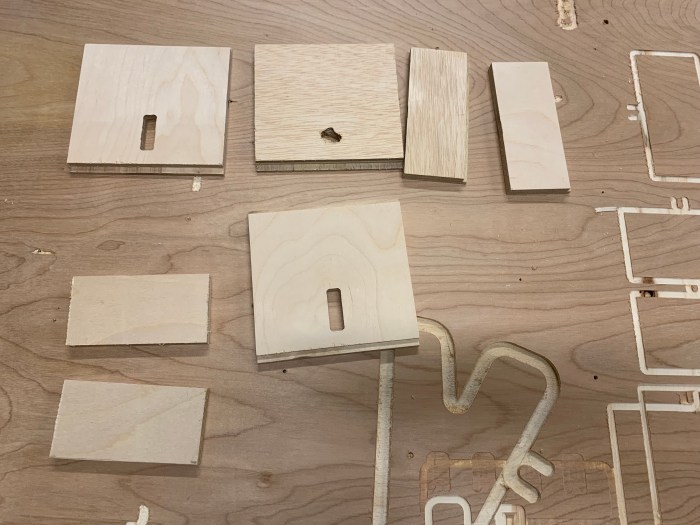
b.) The CNC worked well enough but the rabbet joints were off. The pocket size was not enough for the front panel, so the pieces didn’t fit well. Below are all the parts of version 1 of the sconce enclosure.
c.) An issue midway through cutting was that the bit would fall off. I think this must have something to do with the depth at which it was cutting. Another reason is that the colette is potentially getting loose.
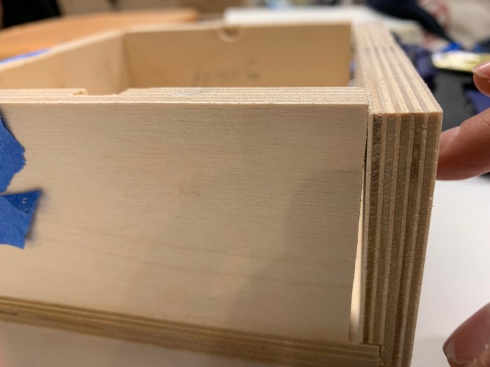
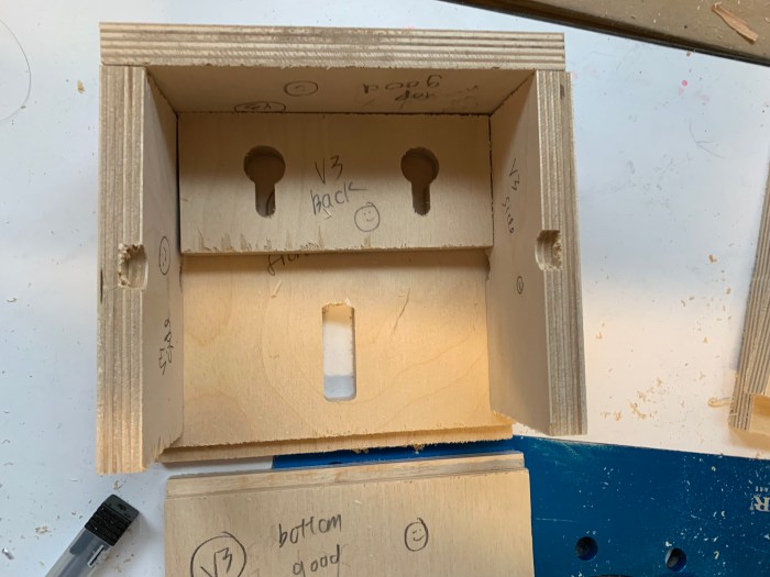
d.) Round 2 begins! Each round I changed the pocket depth cut slightly to see what would work best for the rabbet joint.
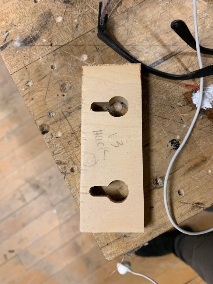
e.) A version 3 set was made. I think between all the sets version 2 and 3 were okay. None were perfect, but after 3 versions I needed to choose.
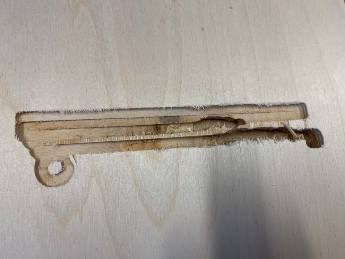
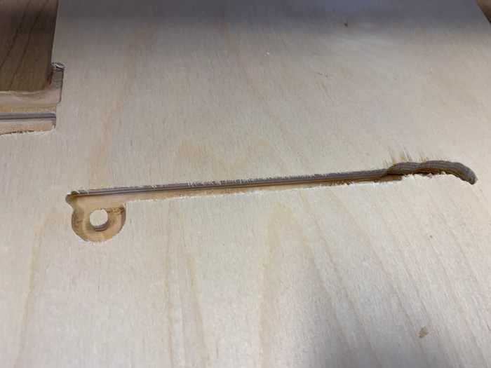
f.) The handle for the key was made by hand because the parts were too small for the CNC. When using the CNC for something this small, the vacuum would accidentally suck up the piece.
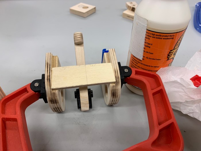
g.) Parts were glued together. Clamps were used.
h.) Sconce enclosure is glued and sanded! Yay!
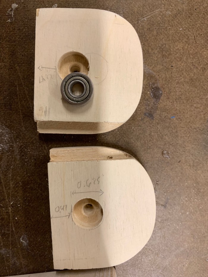
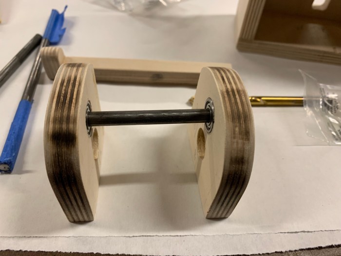
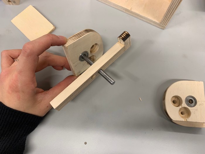
i.) Next, I worked on the key handle mechanism and it’s enclosure. These parts were all hand cut with the band saw and sand blaster.
j.) I used the drill bit to make a pocket for these tiny 3/8″ ball bearings for the rod to go in. The ball bearing is helpful for smoothly rotating the rod that the key handle sits on.
k.) My sconce also includes a photo resistor so that when all the lights in the apartment are turned off the light would also turn off. This small hole was made with a drill press then expanded slightly with a chisel.
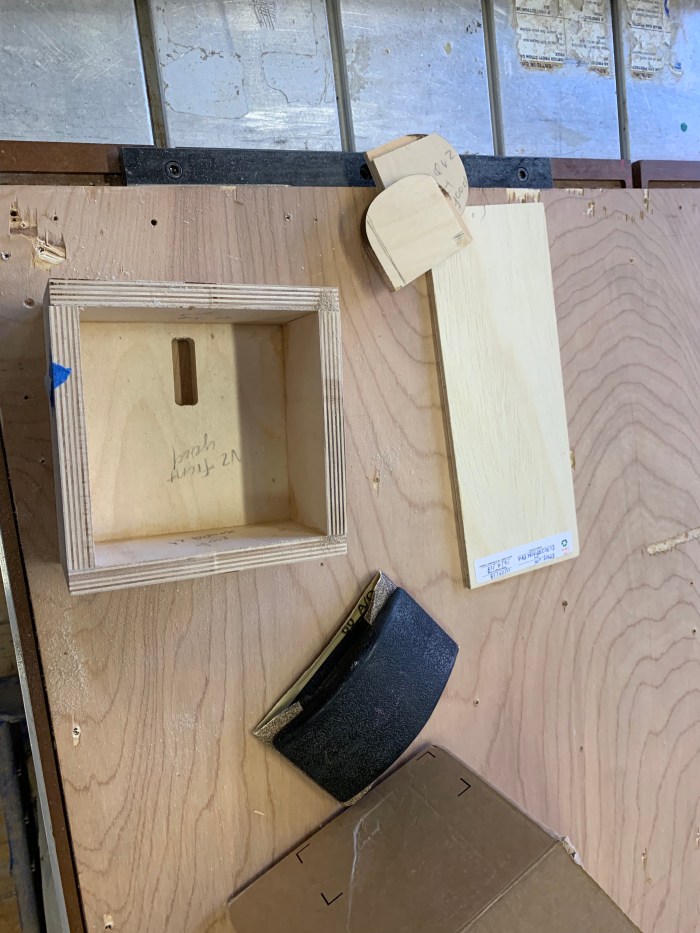
l.) I waxed the enclosure.
m.) I put all the light and electrical components into the enclosure.
n.) Last touch, I glued the screw piece to the back of the enclosure for easy mounting.
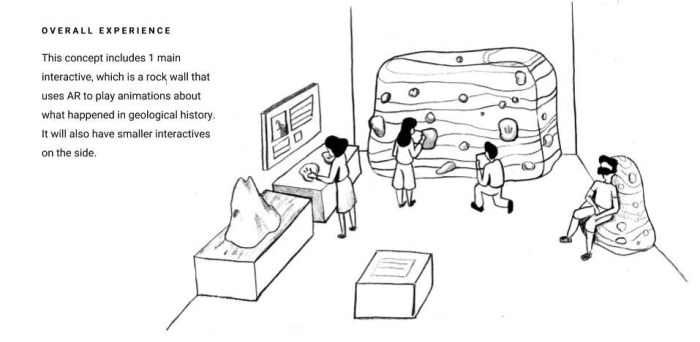
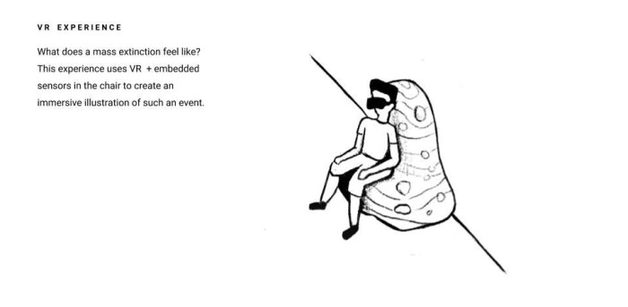
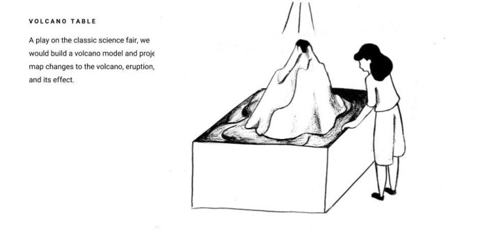
Below are some rough sketches of the overall exhibit design and interactive concepts that our team (Dylan, Maya, Mingna, and I) came up with after brainstorming and meeting with Dr. Rampino.
CNC fun continues! The joinery I worked on this week is for a sconce lighting fixture. I tried out the rabbet joint to fit my pieces together. As usual, I ran into some issues. This time most of my issues were because I only have a 1/4″ bit but many of the joints required a smaller bit size. The joints became too rounded to properly fit together. This all requires some redesign. Nonetheless, I do think I’m getting better at the CAD – CAM – CNC process! Hope I didn’t just jinx it.
First phase was doing a cardboard mockup. Then I did more accurate drawings for the dimensions.
2. I used Vectorworks to make the 2D files first. Then brought it into the CAM software.
3. Screwed down the wood to the spoil board.
4. Brought the files into the CNC software. Started cutting after zeroing.
After cutting, I realized that the joints that I had designed for the side panels were way to small for my bit. This means all the joints were rounded. So I need to figure out a way to create the joints without having rounded corners.