PCM Wk Final 14: Putting it All Together

For this last week, the focus was on all the physical computation and software that was still needed for the interactive. The list includes: a.) finishing all the web pages for the 4 buttons, b.) getting rid of the p5js slider and having it read the analog read serial value, c.) hooking up the buttons with the pages, d.) getting the switches to turn on and off at the right times, e.) the battery function

Almost all wip and final code can be found (still being updated): https://github.com/emilylin-itp/solar

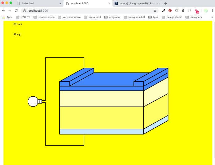
a.) Video below shows the solar cell schematic page working: got rid of the slider, and replaced the slider variable with the variable received from arduino/ serial.

b.)Video below shows the voltage generator page working: arduino is reading the amount of light hitting the solar panel then sending out that variable to p5js which maps it and draws a bar graph.


**** IMPORTANT NOTE! To have the ipad change with the buttons when connected to the webpage via “ip address: local host” you must add this to the js code: “serial = new p5.SerialPort(“ip address”);” This was a big issue, until it wasn’t. Thank you to Professor Shawn Van Every for helping out with that!
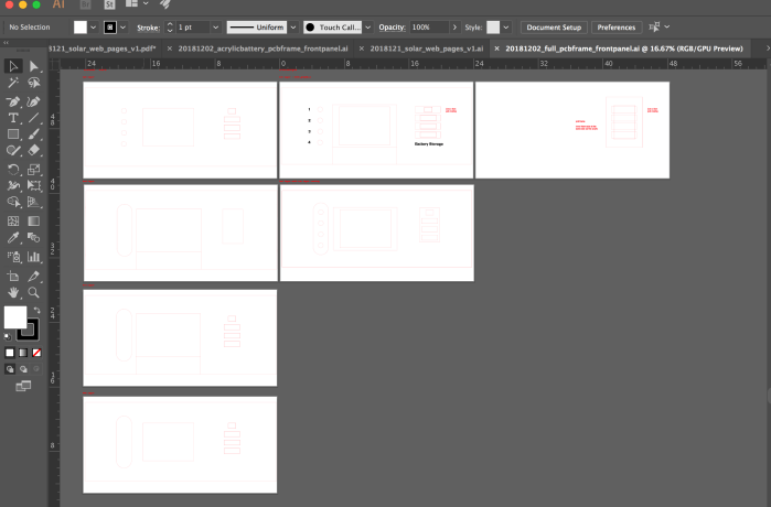
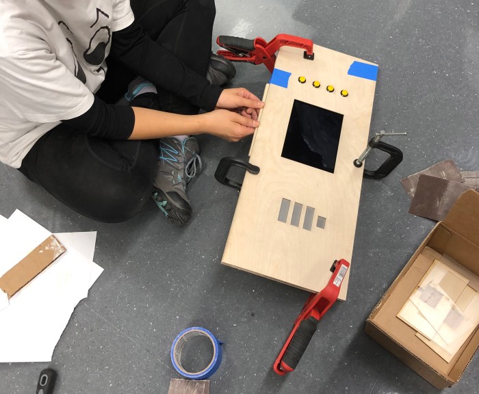
c.) Web pages:

On the icm side, I was working on developing these 4 web pages.  See this ICM post for more details:

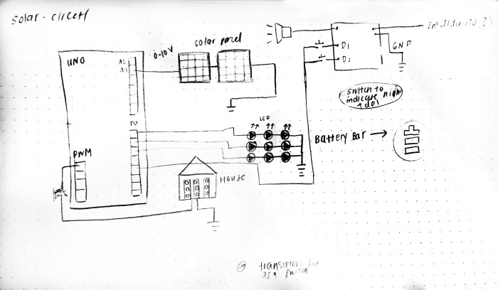
d.) Circuit diagram and notes(without the battery light leds)

This was my first time fritzing, so not sure if it was done properly. Also the 9v is supposed to be 12v but couldn’t find it in the list of components. In the future, I will have to spend more time fritzing because I’m not sure if I have all the right components in here.

fritzing version of circuit

circuit

this below is an updated circuit photo after batteries were added:

IMG_5323.jpg

Attached is a note to self on what each pin on my Arduino Uno has been used for (we managed to use almost all the pins! This is a first for me!) Also included are notes on the order of my console log readings.


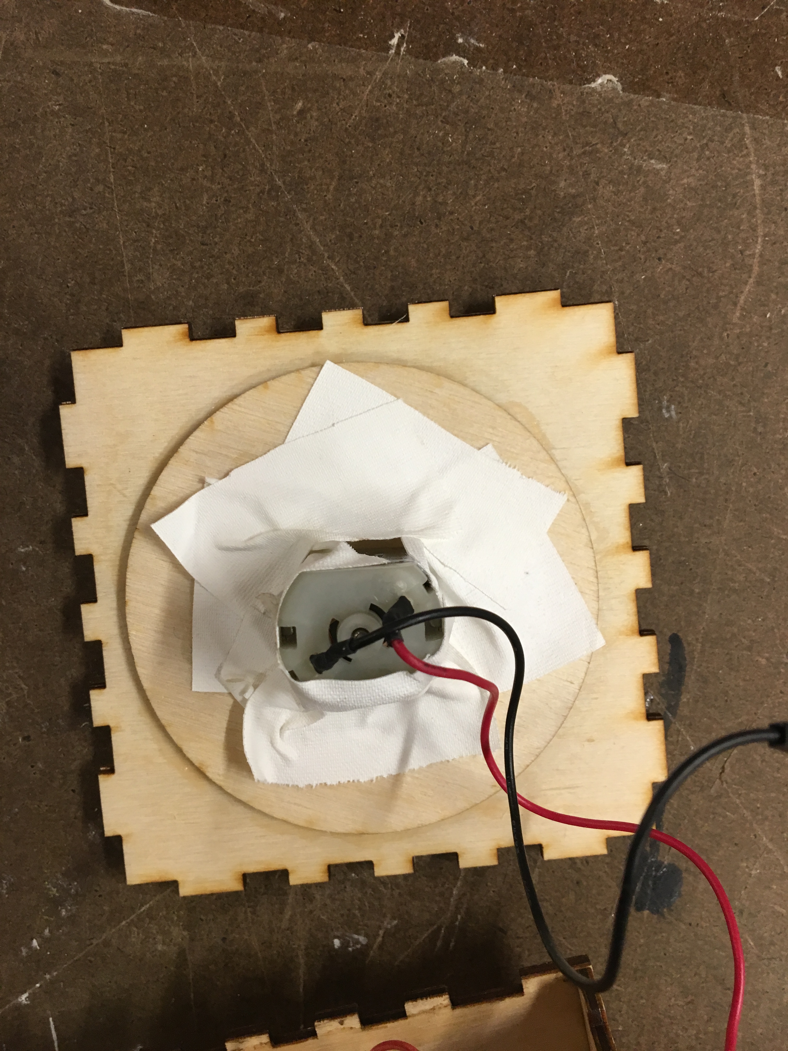
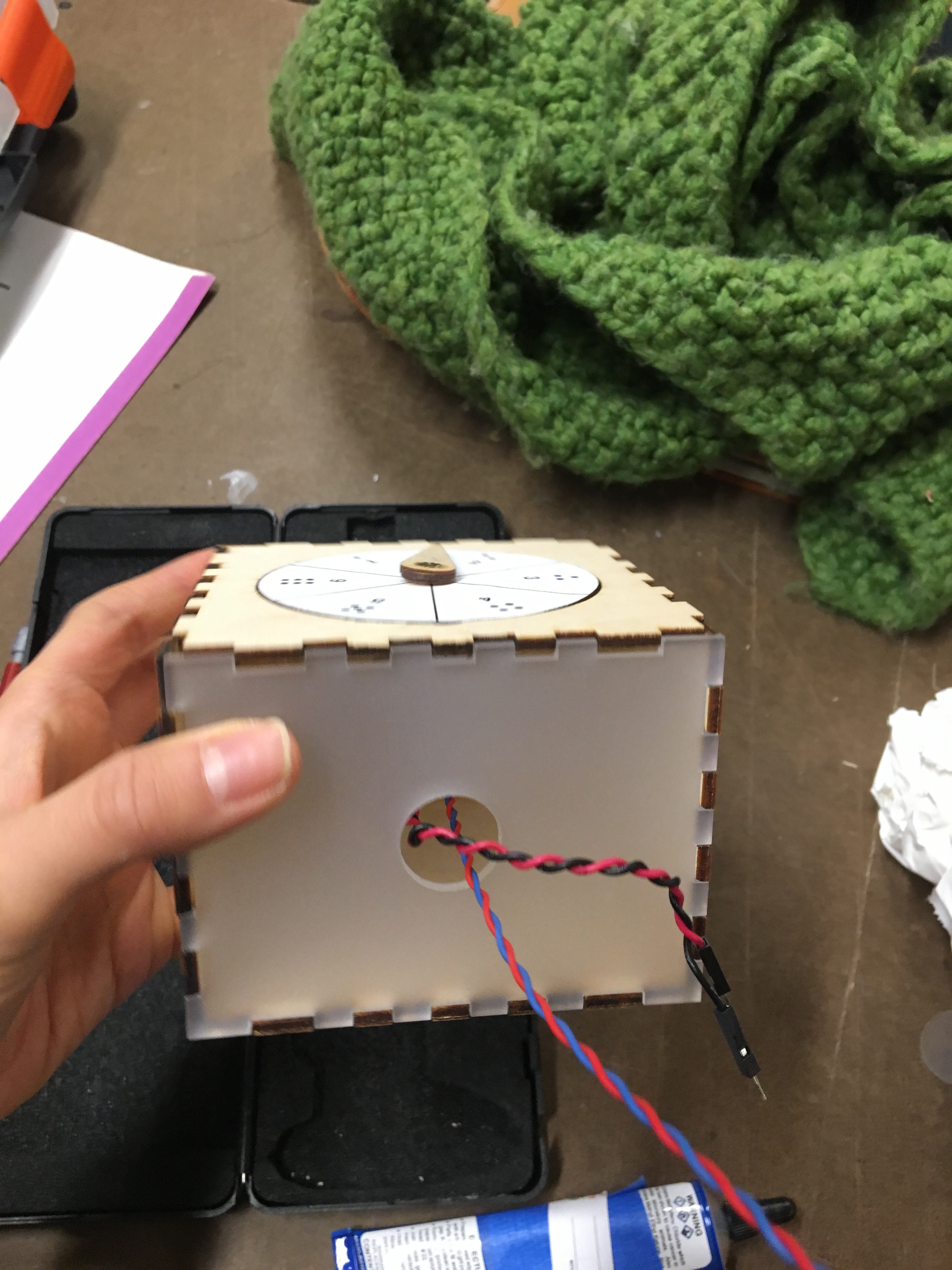
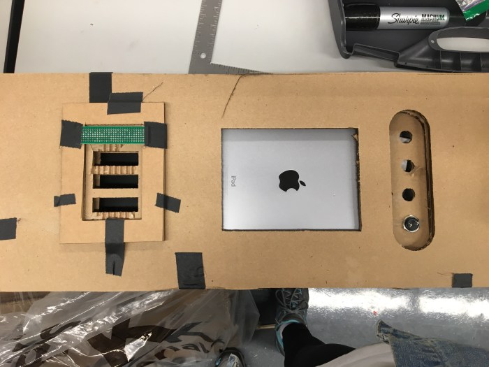
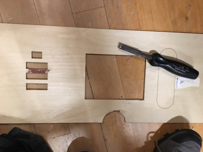
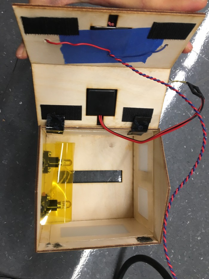
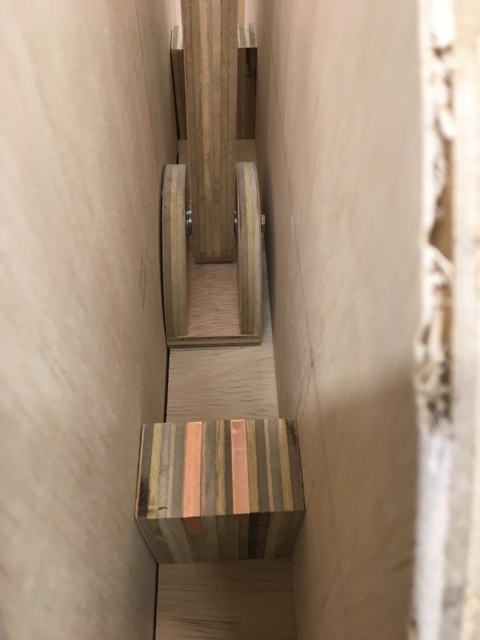
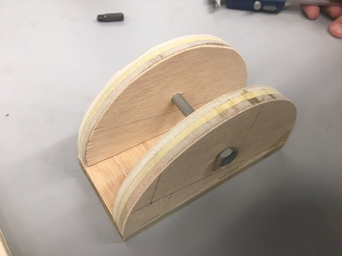
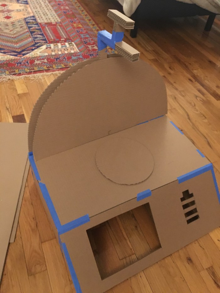
e.) Switches for the Handle:

To create the switches, copper tape was put on the sides of each arm, on both the arm and the block that stopped the arm. This created a push button effect, where the copper tape would short each other and complete the circuit. Thank you Professor Tom for the super helpful advice, this method worked out great. There was also wires attached that went to analog pins (analog only because there were not enough digital pins available). The analog pins were connected to resistors that connected to ground.


c.) Battery Charging/Discharging: this feature was worked on separately from the entire code and physical form that was already set up. Eventually this was combined at the end.

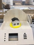
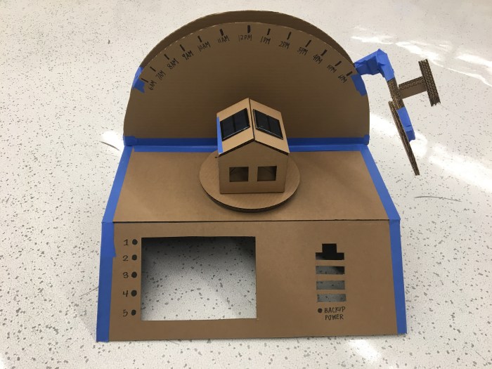
For the battery, the function is that it should be charging (going from bottom to top continuously) until the handle hits the right switch. when handle hits the right switch the battery will discharge and turn on the lights from top to bottom (continuously as well). when the battery is being discharged the house lights will also turn on.

Below is  the code to have the battery charge and discharge based on whether or not the sun is turned on or off. A good reference code was the digital hour glass project of the “Arduino Uno” book:

//SUN control
const int transistorPin = 7; // connected to the base of the transistor
const int leftBar = A4; // connected to the left switch for SUN
const int rightBar = A5; // connected to the right switch for SUN

//button pins
const int button1 = 13;
const int button2 = 12;
const int button3 = 11;
const int button4 = 10;

//house & solar cell pins
const int houseLED1 = 3;
const int houseLED2 = 5;
const int scPin1 = A0;
const int scPin2 = A1;

const int numReadings = 10;
int solareadings[numReadings]; // the readings from the analog input from solar cells
int readIndex = 0; // the index of the current reading
int solarTotal = 0; // the running total
int solarSmooth = 0; // the average smoothed by 10 measurements

//battery parameters

int batBar1 = 2;
int batBar2 = 4;
int batBar3 = 6;
int batBar4 = 8;
int batBars[4] = {batBar1,batBar2,batBar3,batBar4};
unsigned long previousTime = 0;
long interval1 = 2000;
long interval2 = 1000;
int k=0;
int j=4;
//
void setup() {
//configure the digital input:
pinMode(button1, INPUT);
pinMode(button2, INPUT);
pinMode(button3, INPUT);
pinMode(button4, INPUT);
pinMode(transistorPin, OUTPUT);
pinMode(houseLED1,OUTPUT);
pinMode(houseLED2,OUTPUT);
pinMode(batBar1, OUTPUT);
pinMode(batBar2, OUTPUT);
pinMode(batBar3, OUTPUT);
pinMode(batBar4, OUTPUT);

Serial.begin(9600);

for (int thisReading = 0; thisReading < numReadings; thisReading++) {
solareadings[thisReading] = 0;
}
}
void loop() {

unsigned long currentTime = millis();

//SUN control with the left and right switches + battery charge/discharge
int leftSW = analogRead(leftBar);
int rightSW = analogRead(rightBar);

if (leftSW > 600){
digitalWrite(transistorPin, LOW);
for (int n=0; n < 4; n++){
digitalWrite(batBars[n],LOW);
}
//switch to starting page and turn on light and charge battery
k=0;
} else if (rightSW > 600){
digitalWrite(transistorPin, LOW);
if (currentTime - previousTime > interval2) {
previousTime = currentTime;
if (k <= 4){
for (int n=0; n < 4; n++){
digitalWrite(batBars[n],HIGH);
k=5;
}
}
digitalWrite(batBars[j],LOW);
if (j >= 1){
j--;
} else {
j=4;
k=0;
}
}

//switch to battery pg and turn off light and discharge battery
} else{
digitalWrite(transistorPin, HIGH);
if (currentTime - previousTime > interval1) {
previousTime = currentTime;
digitalWrite(batBars[k],HIGH);
if (k <= 3){
k++;
} else if(k = 4){
k=0;
for (int n=0; n < 4; n++){
digitalWrite(batBars[n],LOW);
}
}
}
j=4;
}

Serial.print(currentTime);
Serial.print(",");
Serial.println(previousTime);
Serial.print(k);
Serial.print(",");
Serial.println(j);

// // read the right switch location
// Serial.print(rightSW);
// Serial.print(",");
//
// // read the left switch location
// Serial.print(leftSW);
// Serial.print(",");

}"

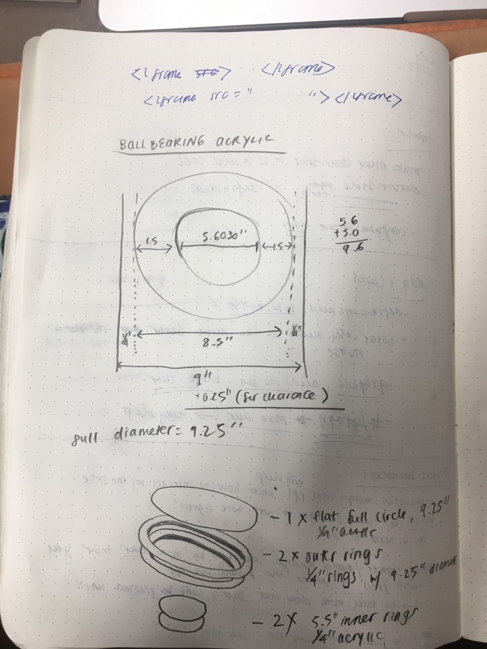
Here is a very rough circuit diagram sketch for how I would wire up and solder the the batteries. I had help from Professor Tom to help me understand what was needed for the leds to switch on and off.

Also, I looked at this helpful lab on transistors for guidance: https://itp.nyu.edu/physcomp/labs/motors-and-transistors/using-a-transistor-to-control-high-current-loads-with-an-arduino/

super rough battery sketch

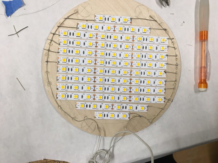
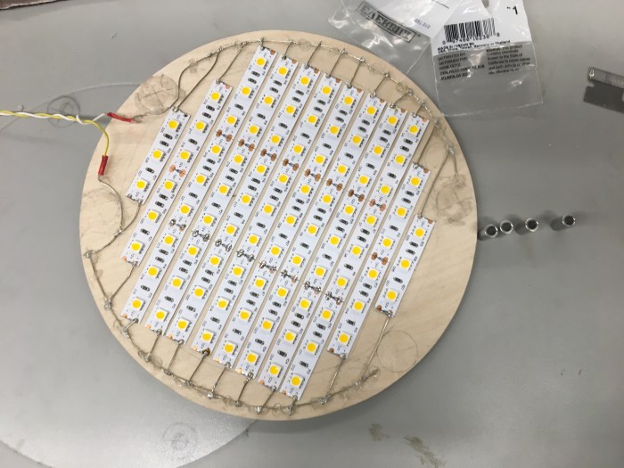
The yellow leds were put in series on 1 row. There are 2 rows per pcb. The power side is connected to the 220 ohm resistor. Then the 2 rows in the pcb were shorted to each other and I attached a wire to both the power and ground side.

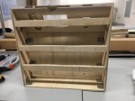
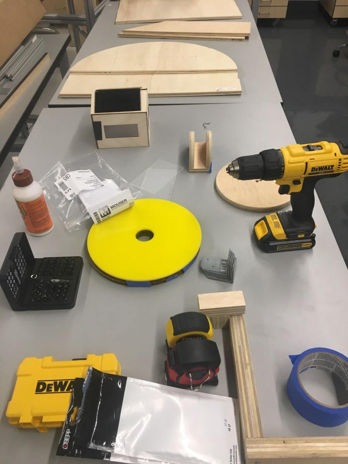
Here are some photos of the process of putting together the led battery lights.


Each pcb board has a transistor paired with it. I connected the negative side to the wire connected to the collector of the transistor. There was a white wire attached to the base of the emitter that is plugged into the digital pins: 2, 4, 6, 8. The black wire is attached to the emitter of the transistor which was all shorted together and plugged into the ground of the dc adapter. the positive side of the leds were then plugged into the positive of the dc adapter.


This slideshow requires JavaScript.

Another 12 volt dc power (separate from the 12 volt dc power for the light source) was used to light up this many leds. One hiccup that happened was the soldering connections. It took so much more time than I thought it would to make these connections and having to see which leds were not soldered properly; therefor affecting all the leds that it is in series with. I also discovered that it is VERY important to solder well and make sure there is a good connection between the wire and the components. The battery lights wouldn’t light up many times, and I had to use the multimeter to check which ones were not connected properly. There are many hiccups to using leds like this, and I almost think it would have been better use led strips, despite how great this dotted yellow light look.


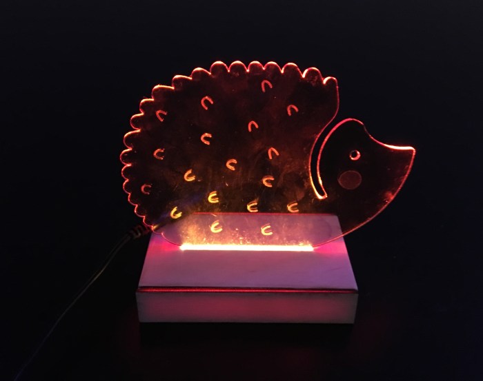
Here is the battery charging in the full setup:


f.) Close to final versions:

Video below shows buttons working but with major delays between ipad and desktop screens.


Below is the latest video but the ipad is not placed properly in the setup, just wanted to show the delay between ipad and Desktop)


g.) Solder to PCB for extra security: tried to be extra careful to completely replicate the breadboard version to the pcb version. It is important that I had a multimeter on hand to check all the connections when soldering.

h.) Reflections:

With my current skill sets, this project was a lot for me to handle in the given time frame but I certainly learned a lot and feel as though I pushed myself.  I probably wouldn’t have taken this idea on if I weren’t at ITP (with all the great professors and people as resources) and if I didn’t have insight from my partner Kasra, who has done materials research on solar cells. I also wouldn’t have felt comfortable doing this without the advice from Professor Tom and Jeff who are very well versed in solar energy. It is important to me that the project was accurate yet fun to play with. Throughout the process I constantly felt myself short on solar energy knowledge. I couldn’t quite decide what to do with certain interactions because I myself was not very familiar with it. It required more research on my end, and with a short timeline I didn’t think I did a good job of learning everything to learn about solar energy. I’m really looking forward to taking the “Energy” course next semester and am hoping that it’ll help me feel more comfortable and well versed in designing for energy-related topics. Even though I was asking the experts around me, my lack of knowledge on this topic made me think this “exhibit” piece was not as educational nor accurate as it could have been.

Another thing I need to watch out for is timing between fabrication and physical computing. I got really into the build and thoroughly enjoyed making the structure for my piece. It was so fun to be in the wood shop learning new tools, making measurements, sketching out diagrams and models. I loved refurbishing my parent’s old furniture, and i think ITP has reminded me of how much I love to make in 3d forms. I spent a lot of time and gave a lot of attention to the fabrication and physical design. But towards the end of the project, I was regretting not allowing myself more time on coding the pcomp side of things. I was rushing through this part, trying to get all the interactions I wanted done (i.e. buttons, switches, battery). I would’ve really enjoyed taking it slower to learn and code with arduino. Coding is fun, but there is still a learning curve for me so it often takes longer than I expect it will. When I’m tied for time I asked people for help, when I wish I could’ve solved it myself (if I had just given myself more time to code). I need to remind myself that it’s important to do the tasks that are harder for myself first, rather than later.

Fab Wk 6: Moods + Mounting Motors

Despite this being the last week of finals and the fact that I’m with a cold, I was super excited to do something with servo motors. I was a little bit more short on time than usual, so I wasn’t able to start till Thursday. I’ve been wanting to make something/ play with servo motors all semester long, and I finally found a good chance to do so. However, I still wasn’t sure what I wanted to do with servo motors so I scavenged the net for some good inspiration on servo projects. I found great examples on the “Make:” site, but eventually stumbled upon this great resource from the site etechnofiles.com: https://etechnophiles.com/top-10-arduino-projects-beginners-2018-honest-opinion/

I really liked project number 8 “Servo motor control with Joystick” and decided I would do a follow along with their tutorial: https://www.youtube.com/watch?v=kA_pbMR6jVs

This was also helpful: https://www.hackster.io/darwindelacruz/how-to-control-single-servo-motor-by-joystick-c57395

Also, remembered the “Mood Cue” project from the “Arduino Uno” book. I was inspired to do my own version that uses icons instead of words and uses a joystick as well!

a.) Inspiration: I saw this great kid’s product online from Counterprint Books studio. I love the design and wanted to somewhat emulate the visual aesthetic of it.

Screenshot 2018-12-14 01.44.19.png

b.) Sketch Idea + Make Measurements:

c.) Prep Illustrator Files Based on Measurements

Screenshot 2018-12-14 02.13.09.png

d.) Make Graphics

Screenshot-2018-12-14-00.26.51.png

20181213_motor_graphic-03-1.png

e.) Set up Arduino + Breadboard (based off videos mentioned above + Arduino Uno book)

IMG_3220


Game Change! Motor Mount for Dice Wheel Box!

So because I am sick, I’ve accidentally slept in (which really rarely happens) the morning of class and did not have time to execute my above mood idea 😦

I really tried though, even thought I slept in I still tried to got to canal plastics and laser cut the piece. Unfortunately, as I don’t think the laser cutters are doing too well. Because I cut 3 times on the acrylic and the hole cutouts still didn’t go through. See image below for proof that the acrylic wasn’t working out to my favor.

To be realistic with time, I decided to change gears (you get it?!) and work on creating a nice mount for my previous project I did for pcomp. I did this project in week 4/5 of this semester, before fabrication. See previous post for it: https://emilylinprocess.blog/2018/10/02/pcm-wk-4-project/

Therefore, my motor was mounted pretty poorly. I just mounted it with very strong tape. See below.

IMG_3224.JPG

So I decided I would make a nice mount to hold the motor in place. I used the caliper to get measurements of the motor.

IMG_3225.jpg

Then I sketched out the measurements and the shape I wanted for the mount. I also drew it on illustrator.

Laser cut this mount. The dc motor fit well in the mount, but the mount itself was slightly too large for the box itself. Therefore, I needed to use the band saw to cut off just 1/8″ off on each end of the motor mount acrylic.

After doing that, I was able to fit the mount nicely in the box and it all fit so well I didn’t need to glue it to the box like I thought I would need to! So this mount needed no glue at all!

IMG_3236.JPG

I also realized after doing this mount, that when I first done this for pcomp I had purposely left out one side because I needed to get access to the arduino. Therefore, one side does not have a face! I decided to go back into my previous illustrator file for laser cutting this piece and make the missing face but with the hole for the wires to go out of the box.

IMG_3238.JPG

Then I glued the top piece, because now that I have the missing side, I could finally glue it down.

IMG_3244.JPG

Here is the final result! This uses the code and breadboard set up from before.

IMG_3252

Fab Wk 5: Materials

For this week’s assignment to use 2 different materials, I decided to use vinyl and cork. I wanted to use this as an excuse to use ITP’s vinyl cutter. When working at a prior job we would always send out our files to have the vinyl cut, so I was determined to learn how this vinyl cutting tool works!

I got the cork from Staples, and decided to make vinyl patterns for the cork coasters.

Below is the process.

  1. I drew simple patterns that I wanted to have vinyl cut on illustrator.

Screenshot 2018-12-07 10.06.11.png

2. Then I watched a bunch of tutorials on how to use the “Silhouette Cameo” vinyl cutter. and downloaded their software onto my laptop. This was incredibly helpful step as I knew so little about this machine. I followed the steps of the tutorial. I imported my png drawing file into the library, traced the image, loaded the vinyl material, did a test cut.

Screenshot 2018-12-07 09.53.24

3. All of this required a lot of troubleshooting and testing to try to get the best results. Loading the material was a trial and error situation of trying to adjust the knobs, the blade setting to optimize the cut. The first video below shows the vinyl paper moving around all over the place, obviously this is my first time.

4. I tried a bunch of cuts and it was still wonky. However, after a couple of different tries and messing around with different settings I eventually got closer to the results I wanted.

IMG_3158

IMG_3157

5. I stuck it onto the cork. Below is a photo of the end result. I didn’t give the project my best try and am not super pleased with my idea or how this turned out. However, I am happy I tried out the vinyl cutter!

PCM Wk 13: Progress Report

Most updated version before user testing on 12/05/18:


Process:

As a way to help me with the many to do items, I have a breakdown of lists that I need to tackle everyday to help me stay on target.

The sheet can also be seen here: https://docs.google.com/spreadsheets/d/1zA4OJrYoYLFRfl6XcdlWMDRCV-Dq8sbgWobO5o2G_kc/edit#gid=1107503517

breakdown of tasks

As shown in the sheet above, there have been different items tackled over the course of a few days, therefore it is hard to pin point chronologically what I started working on. I will try my best to organize and explain the activities that happened throughout the week, though they may not be in order.

a.) Almost immediately after last week’s class, I worked on the light sources for both the house and the “sun” lamp. The full documentation for the light source can be seen in this separate blog post: https://emilylinprocess.blog/2018/11/30/fab-wk-4-enclosures/

b.) I also worked on the front panel, which has many components to consider: the 4 buttons, the battery symbol (with the LEDs in the back), the iPad screen display. For this part, I first started out by measuring out dimensions I needed and sketching out the plans.

There would be four 1/8″ wood pieces that would have a top layer, 2 layers in the middle that would hold the ipad, and a bottom layer. This would act similarly to the halloween midterm crystal ball box – there would be an open slit at the bottom of the front panel that would act like a drawer opening. See sketches below for details.


This slideshow requires JavaScript.

Illustrator file for laser cutting was prepared:

Screenshot 2018-12-03 21.43.14

Cardboard prototype was assembled after laser cutting:

IMG_3025

back of front panel


Then the 1/8″ wood was used for the final. This proved to be very difficult because the laser cutters are extremely slow right now. They must be overused. Anyways, to save time I had to chisel out some parts because the lasers weren’t cutting through.

IMG_3032

Below is the fully functioning ipad drawer. Because I was in a rush there are some issues with it, such as the fact that I forgot a space for the ipad charger. Also it didn’t take into account the safari url bar at the top.

front panel assembling

c.) Light in the house


First was trying the led strips.  Next was the led lamps. These are not the right type of white light (too cool), but they are easier to do gradual changes and they require less volts. I tried to change it using reflective yellow acrylic, but that didn’t look good.

IMG_3098

d.)  Piecing it all together: soldering the wires to the led lamps, adding the copper tapes at the end, adding the buttons, troubleshooting the p5js sketch.


e.) Here is my circuit drawing and also a photo of the wiring of the circuit. Will aim to get a fritzing version soon.

circuit diagram

IMG_3103

Below is an image of how the arduino is hooking up to the house and solar panels.


f.) Here is the code for Arudino:

//pin numbers for PWM of house LEDs
const int HouseLED1 = 3;
const int HouseLED2 = 5;
const int HouseLED3 = 6;

void setup() {
Serial.begin(9600);
pinMode(HouseLED1,OUTPUT);
pinMode(HouseLED2,OUTPUT);

}

void loop() {
int solar1 = analogRead(A0);
int solar2 = analogRead(A1);
int solarAvg = (solar1 + solar2)/2;
int mapSolar = map (solarAvg, 650, 1023, 1, 255);

Serial.write(mapSolar); // binary sent to the computer
// Here you can add more lines for each condition in order to light up more LEDs in the house.
if (solarAvg < 600) {
analogWrite(HouseLED1, 0);
analogWrite(HouseLED2, 0);}

if (solarAvg >= 600 && solarAvg < 780) {
analogWrite(HouseLED1, 50);
analogWrite(HouseLED2, 50);}

if (solarAvg >= 780 && solarAvg < 900) {
analogWrite(HouseLED1, 40);
analogWrite(HouseLED2, 40);}

if (solarAvg >= 920 && solarAvg < 980) {
analogWrite(HouseLED1, 100);
analogWrite(HouseLED2, 100);}

if (solarAvg >= 980) {
analogWrite(HouseLED1, 254);
analogWrite(HouseLED2, 254);}

}”

***

Here is the code to read the analog input through the serial connecter. Repurposed from a previous pcomp/ icm sketch that was done.

let serial;
let portName = ‘/dev/cu.usbmodem1411’;
let inData; // for incoming serial data
let xPos = 0;

function setup() {
serial = new p5.SerialPort();
serial.on(‘list’, printList);
serial.on(‘connected’, serverConnected); // callback for connecting to the server
serial.on(‘open’, portOpen); // callback for the port opening
serial.on(‘data’, serialEvent); // callback for when new data arrives
serial.on(‘error’, serialError); // callback for errors
serial.on(‘close’, portClose); // callback for the port closing
serial.open(portName); // open a serial port

createCanvas(1024,768);
background(255,255,0);
}

function draw() {
// fill(255);
// textSize(60);
// text(“sensor value: ” + inData, 20,100);
graphData(inData);
}

// get the list of ports:
function printList(portList) {
// portList is an array of serial port names
for (var i = 0; i < portList.length; i++) {
// Display the list the console:
print(i + ” ” + portList[i]);
}
}

function serverConnected() {
print(‘connected to server.’);
}

function portOpen() {
print(‘the serial port opened.’)
}

function serialEvent() {
inData = Number(serial.read());
}

function serialError(err) {
print(‘Something went wrong with the serial port. ‘ + err);
}

function portClose() {
print(‘The serial port closed.’);
}

function graphData(newData) {
// map the range of the input to the window height:
var yPos = map(newData, 120, 255, 0, height);
// draw the line in a pretty color:
stroke(0, 100, 255);
strokeWeight(5);
strokeCap(SQUARE);
line(xPos, height, xPos, height – yPos);

// at the edge of the screen, go back to the beginning:
if (xPos >= width) {
xPos = 0;
// clear the screen by resetting the background:
background(255, 255, 0);
} else {
// increment the horizontal position for the next reading:
xPos= xPos + 2;
}
}”

g.) The copper tape / switches: I was able to add the copper switches but I’m still trying to program it so that each switch will turn off the light and show a new screen on the start and end points. Will come soon. Below are some images of the copper tape and plate ready to go.

IMG_3111

Fab Wk 4: Hinge Lamp + Enclosures

For this week’s enclosure project I decided to merge it with the build for my pcomp final. There are 3 enclosures for the pcomp project – one for the lamp, one for the house and one for the entire interactive display. Ideally, I was hoping to finish all 3 enclosures/ the entire build by Friday but hiccups with the production delayed this goal. On the bright side, the hinge lamp arm was completed and the lights are enclosed.

1.) I found some great inspiration from Darbin’s “Building an Articulating LED task Lamp.” I followed along with her great process but made some tweaks here and there.

img_2947.png

2.) First I cut the circle shape for the lamp using a circle jig and hand router (see pcomp blog for details on that).

3.) Next, I mapped out where I wanted my LED light strips to go. After talking with Professor Tom, I got non addressable LED lights. I wanted to make sure that the lights were extremely bright which is why I purchased the 12V LED strips. The idea is that the lamp is supposed to symbolize the sun, therefore I wanted it to be insanely bright; this would also help the solar panels on the house be able get a better sensor reading.

4.) After mapping, I started to cut, place and solder the LED strips onto the wood circle.

56514523720__16FA9A0A-7953-4408-AEC5-B6BBED385063 2

5.) I then placed the magnets onto the wood and tested out how the lights looked with the frosted acrylic circle on top. Based on Darbin’s youtube tutorial, she had magnets as her way of enclosing. She placed lock washers on top of the acrylic to hold it in place. This is why I tried the magnet idea.

6.) I also tested the LED strips by using a dc adapter. This was helpful because I realized one of the strips was not making contact with the wire. I immediately fixed that.

7.) Truth be told, I was disappointed with how the magnets looked. It looked clunky. I received some great advice from fellow ITP first year, Matt, to use standoffs and thin paper on the acrylic for a more diffuse look. I found this to be very helpful advice and got to work on editing the lamp. I had to take of the magnets, do a little rewiring/ hot glue guning.

IMG_2975


8.) Researched a little about what type of enclosure I wanted. At home depot, I decided to get 1/2″ long standoffs to give it distance (for a diffuse look).

9.) Next was marking and drilling holes into the acrylic top.

10.) I used the holes in the acrylic as a stencil for where to drill into the wooden base of the lamp. This included using multiple clamps to help drill into multiple layers.

11.) Then the enclosure was complete! There are certain things I’m not happy with, such as the fact that people can see the ugly glue gun application I did ( if I knew it’d show through so much I would’ve tried to keep the circuit looking pristine!). Another silly mistake I made was soldering the led strips to another thinner piece of wood. I did this because I was hoping that in case anything goes wrong I could easily screw/ unscrew the circle with the lights to the circle without the lights. Unfortunately this creates unevenness when screwing.

I’m thinking of attaching a yellow sheet of flexible acrylic around the edges to hide the circuit and the uneven edges between the 2 circles. Will get clarity on that.

The hinge base for the light arm is a whole other story that lives on a pcomp blog post. Same goes for the entire build. However, the enclosure for this lamp well deservedly went through enough steps to write a whole blog post for! Below are some images of the lamp in the actual setup!

IMG_2992img_3006.jpg

PCM Final Wk 12: Prototype + Progress

Progress:

After the 2nd play test and checking in on the new design with Professor Tom, I started fabricating the parts that I knew would be in the final piece. I knew this build was tough (for me) so I wanted to be sure I started making and ordering materials as soon as possible.

I first started measuring the dimensions based on my cardboard prototype. Instead of having exact measurements to build from, I did things a little differently. I decided to make my cardboard prototype without measuring and just make the box on what felt right for the design and interaction. Then for this final piece, I measured the exact dimensions I wanted based on the prototype. See sketches below.


This slideshow requires JavaScript.

I asked my fabrication professor Mark Kleback, what the best way to go about the semicircle build would be. He recommended I not use the CNC since I don’t know it yet, and use the hand router and circle jig method.

Watched this great video: https://itp.nyu.edu/fab/router-and-circle-jig/ in order to know what I needed to get in order to make this happen. The 2nd year students, Anthony and Amitabh were also amazingly helpful in teaching me this new and exciting tool!

I then started to make all the large structural semi circle pieces. Below is the process. This took some test cuts before I could work on the final cuts, but it worked out well enough!


Next I got to work on the handles. This was done using a mix of the miter saw, band saw and belt sander. See photos below for images of the pieces and result of two 1/2″ wood glued together.


I also got to work on the other large structural elements, such as the top and side panels. The front panel I am saving because I am still waiting on the buttons to come in and the display is now designed in a way that the front panel needs to fit perfectly into the side panels. This can’t be measured until I assemble the structure together. Below is the piece with most of the large structural elements.

structure + house

The house structure was relatively easy, but the roof took a couple of tries to get right. Eventually I had the solar cell fitting perfectly in the cutout of the roof. See image below.


Next was the cover piece for the ball bearing, which I did a cardboard version of first. See process below.

IMG_2916

failed lasercutter

I got to work on the yellow acrylic that would be the material for the final turntable, but the laser cutter took many tries and still wouldn’t cut through. Planning to try another time. In the meantime, the cardboard will have to do.

Now that I had the structural parts (minus the front) I began the assembling of the main big pieces.

set up for assembling

Assembling required corner brackets to hold the pieces together at 90 degree angle.

corner brackets for structure

Next was also assembling the hinge base for the handle. From assembling it I realized some issues that would have to be addressed- the space between the handle and the base was a little too large. There will need to be extra washers added to make that space perfectly tight.

IMG_2936

Now, almost all the structure is in place. Parts missing and art still in progress: the front semi circle, which will be attached to some inside bars for support. It is also so that the hinge will be easily accessible from the back. Also the front display panel where the ipad and battery symbol will go.

structure

More to come on all ends (circuit, fabrication and coding)!


ICM Final Week 12: In-Class Play Test

Explanation:

For the play test today (11/27/18), I showed users my cardboard prototype (version 2 with the circular set up with the sun dial light). I had a slider version working for the photons, so that when users shined more light on the solar panels I would manually move the slider to create more photons. I am still trying to figure out how to generate more electron-hole pairs after the photons hit the solar cell. Next will be to have the solar panel sensor reading tie in with the sketch (in replacement of the slider).

Below are the 3 parts of what I presented today – a.) the build, b.) the p5js animation with the slider, c.) the illustrator file with the text overlay.

a.) the build

prototype after play test

b.) the p5js animation


c.) the illustrator file with the text overlay that correlates with the buttons on the display and the the # on the screen.


Reflections after play test:

Today’s play test was incredibly helpful. Everybody provided great feedback about the parts that were confusing and could be improved upon. The biggest takeaways were:

1.) Many people were confused about what the screen was showing. Right now, it is just showing a schematic of a blown up cross section of a solar cell. However, many people thought that only the top blue layer was the solar panel (which makes complete sense!).  I need to somehow indicate that this is a cross section of the solar cell, not the solar panel on a house. Suggestions included: adding a house in the background to show that this solar cell was taken from the house, making the solar cell look more like a solar panel, text that clearly tells people this is a solar cell schematic.

2.) The battery storage needs to be more clear what will happen. The issue of what happens when people press the battery button when the light is on needs to be worked out. There are 2 options that this could go in: 1.) there could be a separate graphic that shows up that says what actually happens when the battery is being used when there is light on, 2.) get rid of the analog battery option and only allow people to select the battery option through the screen.

3.) Will it be clear enough to just have lights that dim and get brighter based on the light source? Is it worth putting a numerical value or bar graph that very very clearly shows that the light shining on the panel directly impacts the sketch? I will definitely still have the solar cell schematic because that is the main education takeaway. Should I add a new web page that shows the number or a graph?

4.) Dana mentioned a great point about having an opener graphic/ page that helps people know what this is interactive is about and how to play with it. It would be weird for people to just be introduced with this schematic, so perhaps adding an introduction of some sort. “Think of it like a book” were her exact words, which really helps me think about the curating the narrative that people should experience.

5.) People didn’t immediately realize that you could rotate the turn table, so maybe including arrows on the turn table that indicate you can move it.

ICM Final Wk 10-11: Progress

This is an update on the progress I’ve made thus far on the schematic and website of the solar project.

1.) First things first was to just quickly mockup in Illustrator and Sketch what I wanted the design to look like. I tackled it in Illustrator initially since I’m faster there and because it is somewhat difficult to illustrate shapes in Sketch. Then I copy and pasted the vector shapes into Sketch to be able to get the exact coordinates. Small design changes were made to help me be more accurate.

sketches for websiteScreenshot 2018-11-18 19.28.40

2.) My next important step was to make a list of to do items to tackle for the weekend.

IMG_2827

3.) I then got to work on my first step: drawing the solar cell schematic. Using the coordinates off of sketch I was able to have a rough estimate of where to put the shapes based on the canvas size of a tablet (1024 x 768 px). Some coordinates for the shape were still unknown so I still needed to calculate and map them out.

map of drawing's coordinates

4.) I decided to work on Atom this time, because I wanted to get comfortable with using a text editor and being able to connect to the site through the local host. I also added text for the coordinates as a guide to help me with drawing. See below for sketch.

Screenshot 2018-11-18 19.27.33

5.) I also tried to center the drawing on the canvas using this positioning your canvas code I found: https://github.com/processing/p5.js/wiki/Positioning-your-canvas. I also used beginShape(), endShape() so that in case I need to move or scale the schematic I could easily do so even though I hard coded coordinates.

6.) After finishing the drawing, I tried to make the animated waves for the photons coming from the sun. I did this in a separate sketch file. I refracted the code from a codepen piece: https://codepen.io/xhepigerta/pen/EWZMLE

7.) I made a separate sketch just to get an animated moving arrow: https://editor.p5js.org/elinsterz/full/SJvNQTJC7

Here it is combined: https://editor.p5js.org/elinsterz/full/Hyu3g0yAX 

7.) A separate sketch for the part where the electron moves through the circuit: https://editor.p5js.org/elinsterz/sketches/rkecEHER7

8.) A separate sketch for the part of the animation that requires the electrons (placed in different locations) to travel to the beginning of the circuit that is on the front contact. I just focused on the code for “tweening”, since I would need to change the start and stop coordinates once I combine the sketch.

Code: https://editor.p5js.org/elinsterz/sketches/HyS4EEIRm 

9.) Now that all the animation elements are in their own sketch files, it is time to combine them all into one code. In order to have my code be easier to manage, I transferred the files onto Atom and am coding from there now.

I first created a class for the photon, the electron, the sun, and the cell drawing. the electron class has multiple functions, such as tweening, generate and circuit.

Then, I strung the sequences together in the “sketch.js” file using boolean statements that trigger a bunch of if statements.


10.) The hard next step was trying to get the animation to loop through after one round. I had to reset the variables and have the boolean statement return back to true. Below is the result of that:


11.) Next, is trying to create a slider version that will loop. This requires a lot of revisiting classes and trying to read where the photon position lands in order to generate the electron hole pairs. The struggle is currently still continuing, but so far I have the slider generating more photons. Next step is having each photon that is generated also create an electron hole pair that loops through the circuit.


PCM Final Wk 11: Playtest, Revisions, Prototype

Playtests:

My first play test for the solar interactive was extremely helpful. Since I last blogged, the idea has changed from using the polarizing filters within the box format to having a rotating light source that users could interact with. Below is a video of what I had play tested (minus the flashlight and screen).


The play test in class on Wednesday, 11/13/2018, was very helpful. The biggest takeaways were:

  1. Everyone pressed the battery button first. This was not the intention. I need to make it more clear that the button is for backup storage. Perhaps the battery will light up when there is no light. One user suggested that he would like to see the battery being charged when there is light shining on the house; this I think was a good suggestion.
  2. Users felt a disconnect between the screen + model. People often focused fully on either the house or the screen. There has to be a good enough reason for people to look at the screen, so have more connection between the two or add more info.
  3. Users liked the idea of having the moveable light source be on a track, they all agreed it would be more fun.
  4. A few users mentioned that they would like to see a # that tells them how much energy is being generated from the solar panels.

After the play test, I immediately focused on redesigning the interactive so it would be: 1.) Making the battery interactive less important and a secondary element, 2.) Connecting the screen with the house, 3.) prototyping the light on a track or handle idea and connecting it with time of day.

Below are a few sketches that try to solve for these issues:


After creating many sketches of the model I wanted, I focused on creating a working prototype. I was especially looking forward to prototyping the handle, because that was the hardest part for me to visualize in my head. Below are some process photos.

IMG_2767


Below is a look at how the handle was put together. I placed the lock washer and washer on both ends of the bolt. I had to tighten the nut a lot in order for the handle to stay in place when my hand wasn’t holding it.


I am thinking that the lamp could be made of LED strips. On making this handle and trying to understand how to make the lamp, I used this video as a resource (also, how cool is Darbin?!) : https://www.youtube.com/watch?v=XHeJn1Hnfh0

However, my version has less arms and rotates on y axis, not z or x. I also intend for mine to be in a circular shape. Like her, I will also use plexiglass with magnets as a way to protect the LED lights, and I will use the eyelet hooks as a way to string the wire along the handle.

After assembling it all together, I tried play testing again on Monday (11/19/18). Here’s how it went:


This was helpful, but I do think it would’ve been more informative if I had a working version of the screen. Currently, making moves on the ICM front as well. Much more to do!


Fab Wk 3: Laser Cutting

For this week’s project to work with the laser cutter, I used laser cut acrylic and LED strips to create a light box. I jumped around between several ideas, but eventually landed on the idea of doing animal shaped night light/ light box.

Final result:

IMG_2796

final hedhego

Process: 

  1. First was sketching out the animals on illustrator. I tried to keep the style simple and graphic. I played around with the idea of making an oil diffuser with these wooden laser cut leaves in a jar, which is why there is a leaf on the side. Eventually that idea was dumped. The blue are the small marks for the engraving. I thought it’d be nice to add some minimal lines and textures.

Screenshot 2018-11-15 11.56.11

2. Then I laser cut a cardboard prototype of the animal (just to be safe).

IMG_2769

3. Next was making the laser cut acrylic version.

acrylic laser cut

4.) Then I measured and calculated the dimensions for the lightbox using Illustrator.

5.) I laser cut the box using 1/8″ wood. Then I soldered my LED strip to the adaptor cable and attached it to the wood base.


6.) Last part was assembling it all together and making sure the light works. And it did!

This slideshow requires JavaScript.